Ancient building repairing and correcting equipment
A technology for ancient buildings and equipment, applied in the field of ancient building repair and correction equipment, can solve problems such as corrosion and weathering, building surface damage, and threatening life safety.
- Summary
- Abstract
- Description
- Claims
- Application Information
AI Technical Summary
Problems solved by technology
Method used
Image
Examples
Embodiment 1
[0040] as attached figure 1 to attach Figure 12 Shown:
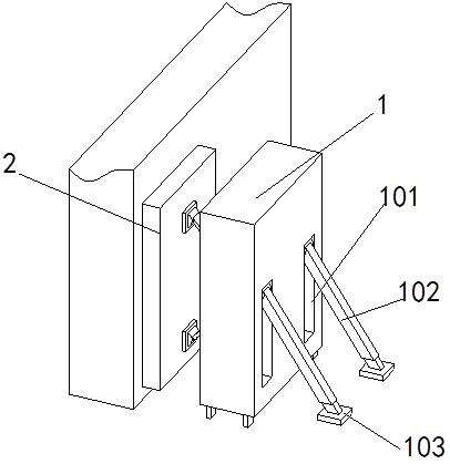
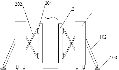
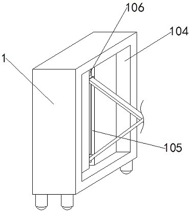
[0041]First, push the present invention to both sides of the wall to be supported, take out the bracket 102 in the bracket groove 101 on the back of the equipment box 1 and stretch it so that the legs 103 touch the ground to provide the back support for the equipment box 1, and then pass the control The hydraulic pump 302 works to make the telescopic rod 303 contract and drive the movable seat 301 to move along the movable chute 105. At this time, the angle between the connecting rods 202 connected with the movable seat 301 will be changed, so that the top plate 2 stretches out against the building. wall.
[0042] When the movable seat 301 moved along the movable chute 105, the guide roller 310 in the equipment plate 304 inside it would engage with the side wall of the liquid storage compartment 107, and the guide teeth 311 on the roller body of the guide roller 310 would pierce into the Connect the guide column 113 ...
Embodiment 2
[0044] as attached figure 1 , 2 , 13 to attached Figure 17 Shown:
[0045] When the building wall was extruded to be vertical by the top boards 2 on both sides, the horizontal liquid in the horizontal detection cabin 204 in the top of the top board 2 would also be in a horizontal state. The level sensor 209 is in contact, so that the liquid level sensor 209 transmits a signal to the electric lock 205 to make it control the dead bolt 211 at the top of the lock cylinder 210 to enter the inside of the lock cylinder 210. At this time, the correction plate 206 releases the restriction of the electric lock 205 and will be in the elastic conduit 207. Driven to move towards the through hole 203, so that the electric telescopic tube 214 in the correction plate 206 stretches out of the through hole 203, and the correction and repair plate 217 at the top of the auxiliary pipe 215 is pressed against the wall surface, and the connecting rod 202 is connected by the elastic conduit 207. ...
Embodiment 3
[0047] as attached Figure 17 Shown:
[0048] After the correction plate 206 is unlocked, the electric telescopic tube 214 on the plate will stretch out of the top column 2 through the through hole 203. At this time, the correction and repair plate 217 on the top of the auxiliary pipe 215 will be against the brick in the wall surface. If the brick If the connection between the blocks is not flat, then the rectifying and repairing plate 217 will be in an inclined state under the action of the rotating shaft 216. At this time, the electric telescopic tube 214 will stretch out the secondary pipe 215 according to the state of the rectifying and repairing plate 217 to push the rectifying and repairing plate 217 to push the brick, After the rectification repair plate 217 is in a vertical state, the electric telescopic tube 214 stops working, and the effect of leveling the uniformity of the wall can be achieved.
[0049] Working principle: first push the present invention to both si...
PUM
 Abstract
Description
Claims
Application Information
 - R&D
- Intellectual Property
- Life Sciences
- Materials
- Tech Scout
- Unparalleled Data Quality
- Higher Quality Content
- 60% Fewer Hallucinations
Browse by: Latest US Patents, China's latest patents, Technical Efficacy Thesaurus, Application Domain, Technology Topic, Popular Technical Reports.
© 2025 PatSnap. All rights reserved.Legal|Privacy policy|Modern Slavery Act Transparency Statement|Sitemap|About US| Contact US: help@patsnap.com


