Lamp lifting device

A technology for lifting devices and lamps, which is applied in the direction of lighting devices, lighting auxiliary devices, lighting device components, etc., can solve problems such as affecting lifting, poor stability, and mutual winding, and achieve good functional effects and improve safety and stability.

Active Publication Date: 2021-10-22
浙江恒熙光电科技有限公司
View PDF6 Cites 0 Cited by
  • Summary
  • Abstract
  • Description
  • Claims
  • Application Information

AI Technical Summary

Problems solved by technology

In response to the above situation, a lifting device for high-altitude lighting has been developed, but because it needs to be used in high-speed rail stations, airports and other environments, it requires high safety requirements, and the existing lifting device usually only lifts through a simple single cable , the stability is poor, and it does not have the function of anti-falling; and in use, it is found that when the steel cable is wound on the reel, it is easy to intertwine in disorder, and the winding will affect the lifting, so it needs to be improved

Method used


Image

  • Lamp lifting device
  • Lamp lifting device
  • Lamp lifting device

Examples


Embodiment 1

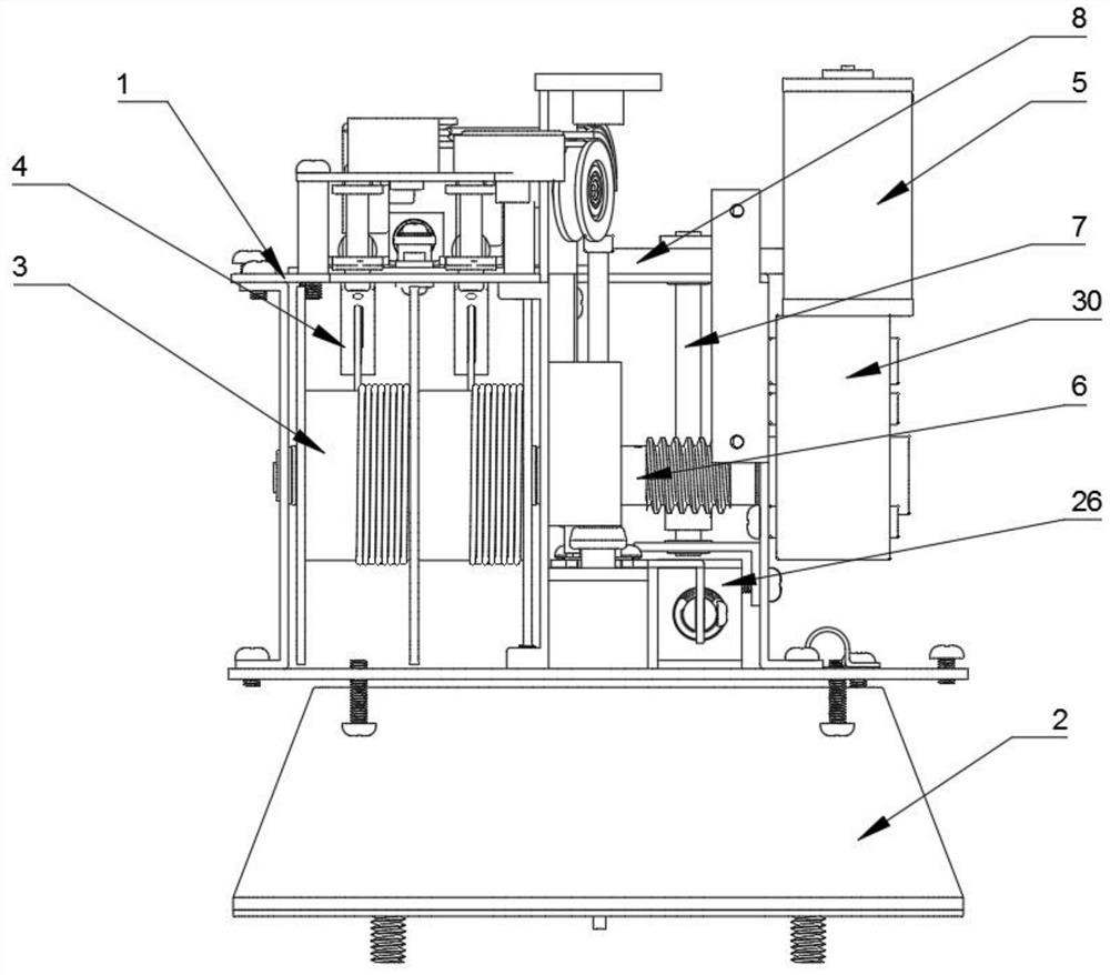
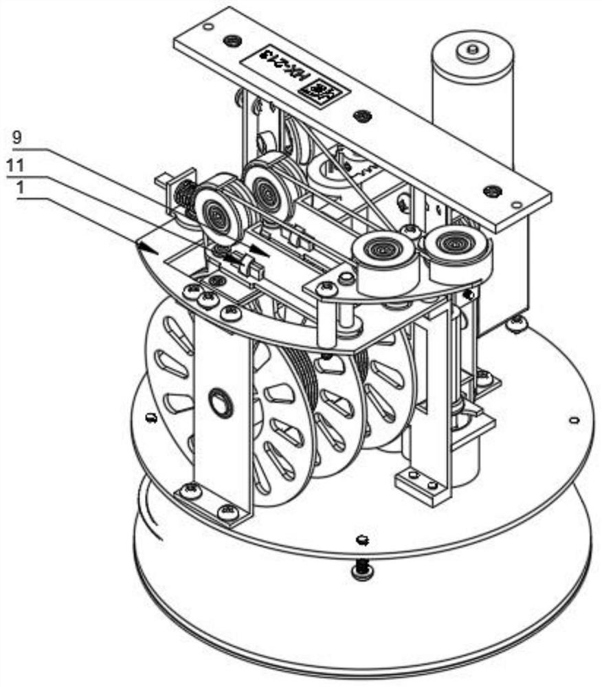
[0057] A lamp lifting device, comprising a main body and a lamp holder 2 placed under the main body, a traction rope for pulling the lamp holder 2 up and down is also provided in the main body, and a fixing frame 1 is also arranged in the main body, and the feature is that the fixing frame 1 is equipped with a double cable traction and winding device and an anti-winding device. The double-steel cable traction and winding device includes a double-slot steel wire reel 3 and a driving mechanism for driving the rotation of the double-slot steel wire reel 3. The anti-winding device includes a guide mechanism and the reciprocating mechanism used to drive the guide mechanism to reciprocate, the upper end of the traction rope passes through the guide mechanism and is fixedly wound on the double-slot steel wire reel 3, and the lower end of the traction rope is connected to the lamp holder 2.

[0058] This device can control the up and down of the lamp holder 2, and the corresponding lig...

Embodiment 2

[0073] During use, Embodiment 1 still has some defects. For example, in the process of raising or lowering the lamp, there may be problems such as open-loop failure of the stroke, unexpected power failure, jamming of the cable lifting, etc., which will cause damage to the motor 5 or accidents. Problems such as falling, so further improvements are made on the basis of Embodiment 1:

[0074]Between the described motor 5 and the main transmission shaft 6, a reduction box 30 and a transmission protection mechanism are also arranged successively. The output ends are connected, and the other end of the transmission rod 31 is arranged in the sliding sleeve 32, and the end of the transmission rod 31 located in the sliding sleeve 32 is provided with a limit block 34, and the transmission rod 31 is also sleeved with a sleeve connected to the inner wall of the sliding sleeve 32. The blocking sleeve 35, the two ends of the pre-tightening spring 33 are in axial conflict with the limit bloc...


PUM


Abstract

The invention discloses a lamp lifting device. The lamp lifting device is characterized in that a motor is controlled to rotate forwards or backwards in a remote control mode or a drive-by-wire mode to enable a double-groove steel wire reel to unwind or wind steel wires synchronously, so that a lamp holder where a lamp is hung is lowered or lifted. The lamp lifting device has the advantages of being simple in structure, stable in work, capable of achieving double-steel-wire double-self-locking falling prevention, and extremely high in safety and high. The lamp lifting device is suitable for places with dense personnel or high safety requirements, such as high-speed rail stations and airports, and is convenient to popularize and use. According to the technical scheme, the lamp lifting device comprises a main body and a lamp holder arranged below the main body, wherein the main body is further internally provided with a traction rope used for pulling the lamp holder to ascend and descend and further internally provided with a fixing frame; a double-steel-wire traction winding device and an anti-winding device are arranged on the fixing frame; the double-steel-wire traction winding device comprises the double-groove steel wire reel and a driving mechanism used for driving the double-groove steel wire reel to rotate; and the anti-winding device comprises a guide mechanism and a reciprocating mechanism used for driving the guide mechanism to move in a reciprocating way. The lamp lifting device is suitable for the technical field of lifting devices.

Description

technical field [0001] The invention belongs to the technical field of lifting devices, in particular to a lifting device for lamps. Background technique [0002] Remote control lifting lights are usually used in large high-speed rail stations, large venues, large factory buildings, airports and other places and the lamps are fixed to the top of the building beams. When the lamps are installed in a higher space, they must be maintained by special lifting equipment or through scaffolding. In response to the above situation, a lifting device for high-altitude lighting has been developed, but because it needs to be used in high-speed rail stations, airports and other environments, it requires high safety requirements, and the existing lifting device usually only lifts through a simple single cable , the stability is poor, and there is no anti-drop function; and it is found in use that when the steel rope is wound on the reel, it is easy to intertwine in disorder, which will aff...

Claims


Application Information

Patent Timeline
Patent Type & Authority Applications(China)
IPC IPC(8): F21V21/38
CPCF21V21/38
Inventor 裘君超
Owner 浙江恒熙光电科技有限公司
Why Eureka
Try Eureka