Movable friction stir welding device with automatic transfer function

A friction stir welding and welding device technology, which is applied in welding equipment, manufacturing tools, non-electric welding equipment, etc., can solve the problems of lifting the center of gravity of the equipment, not having the function of walking and transferring, and the wear of the suction cup to achieve good stability.

Pending Publication Date: 2021-10-26
湖南智能焊接研究院有限公司
View PDF1 Cites 0 Cited by
  • Summary
  • Abstract
  • Description
  • Claims
  • Application Information

AI Technical Summary

Problems solved by technology

[0003] Conventional mobile friction stir welding equipment does not have the function of walking and transporting, and must rely on manual lifting, which is very inconvenient in actual use
In order to overcome this difficulty, mobile friction stir welding equipment (such as the Chinese patent application No. 201420808779.5) that can move with the help of rollers has appeared. The mixing head is off the ground to avoid the wear of the suction cup caused by dragging on the ground
This switching method will lead to a substantial increase in the center of gravity of the equipment, thereby reducing the stability of the equipment during transfer and may cause the equipment to overturn

Method used


Image

  • Movable friction stir welding device with automatic transfer function
  • Movable friction stir welding device with automatic transfer function
  • Movable friction stir welding device with automatic transfer function

Examples


Embodiment Construction

[0025] The present invention will be further described in detail below in conjunction with the accompanying drawings and specific embodiments.

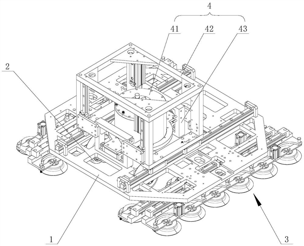
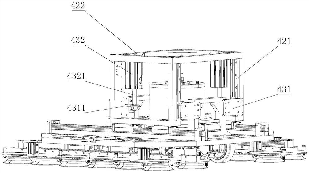
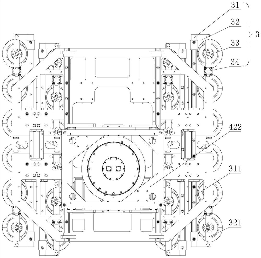
[0026] Such as Figure 1 to Figure 5 As shown, the mobile friction stir welding welding device with self-transfer function in this embodiment includes a frame 1, a roller 2, an adsorption mechanism 3, and a welding actuator 4; the roller 2 is installed at the bottom of the frame 1 to align the frame 1 for support; both the adsorption mechanism 3 and the welding actuator 4 are movably connected with the frame 1; in the walking state, the adsorption mechanism 3 and the welding actuator 4 move upward to leave the ground, and the rollers 2 drive the frame 1 to move.

[0027] During the welding process, the adsorption mechanism 3 crawls on the workpiece to be welded to stably drive the equipment to move along the weld seam, while the welding actuator 4 continuously welds the workpiece to be welded, so that uninterrupted welding can be real...


PUM


Abstract

The invention discloses a movable friction stir welding device with an automatic transfer function. The movable friction stir welding device comprises a rack, rolling wheels, an adsorption mechanism and a welding executing mechanism; the rolling wheels are arranged at the bottom of the rack so as to support the rack; the adsorption mechanism and the welding executing mechanism are both movably connected with the rack; and in a walking state, the adsorption mechanism and the welding executing mechanism move upwards to be separated from the ground, and the rolling wheels drive the rack to move. When equipment needs to be transferred, the adsorption mechanism and the welding executing mechanism are lifted to be higher than the bottom ends of the rolling wheels, at the moment, the rack is completely supported by the rolling wheels, and the equipment can walk and be transferred under the driving action of the rolling wheels. Compared with the prior art, when the movable friction stir welding device with the automatic transfer function is converted into the walking state, the whole set of equipment does not need to be jacked, only the adsorption mechanism and the welding executing mechanism need to be slightly lifted to be separated from the ground, and compared with the prior art, the gravity center lifting amplitude of the movable friction stir welding device is far smaller than that of the prior art, and the stability is better.

Description

technical field [0001] The invention mainly relates to the technical field of mobile friction stir welding, in particular to a mobile friction stir welding welding device with self-transfer function. Background technique [0002] Friction stir welding uses the heat generated by the friction between the high-speed rotating welding tool and the workpiece to partially melt the material to be welded, and moves along the gap to be welded through the welding tool, and the plasticized material is passed by the front of the welding tool under the action of the rotating friction of the welding tool. The part flows to the rear and forms a dense solid-phase weld under the extrusion of the welding tool. This welding technology has the advantages of no spatter, no smoke, no porosity, no slag inclusion, no need for filling materials and shielding gas, low energy consumption, no pollution to the environment, etc., and has broad application prospects. [0003] Conventional mobile friction ...

Claims


Application Information

Patent Timeline
Patent Type & Authority Applications(China)
IPC IPC(8): B23K20/12B23K20/26
CPCB23K20/1245B23K20/26
Inventor 雷智斌蒋习均黄韬苏俊伟
Owner 湖南智能焊接研究院有限公司
Why Eureka
Try Eureka