Movable friction stir welding machine frame

A technology of friction stir welding and frame, which is applied in welding equipment, non-electric welding equipment, metal processing equipment, etc. It can solve the problems that the welding parts cannot be welded and the whole process of welding cannot be realized, and achieve the effect of uninterrupted welding

Pending Publication Date: 2021-11-02
湖南智能焊接研究院有限公司
View PDF0 Cites 0 Cited by
  • Summary
  • Abstract
  • Description
  • Claims
  • Application Information

AI Technical Summary

Problems solved by technology

In order to ensure that the welding equipment is firmly fixed on the piece to be welded to avoid dumping, the crawler mechanism must be mostly adsorbed on the piece to be welded. The resulting problem is that the edge position of the piece to be welded cannot be welded, resulting in the beginning / When the end is finally to be welded, existing welding equipment cannot achieve full welding

Method used


Image

  • Movable friction stir welding machine frame
  • Movable friction stir welding machine frame
  • Movable friction stir welding machine frame

Examples


Embodiment Construction

[0022] The present invention will be further described in detail below in conjunction with the accompanying drawings and specific embodiments.

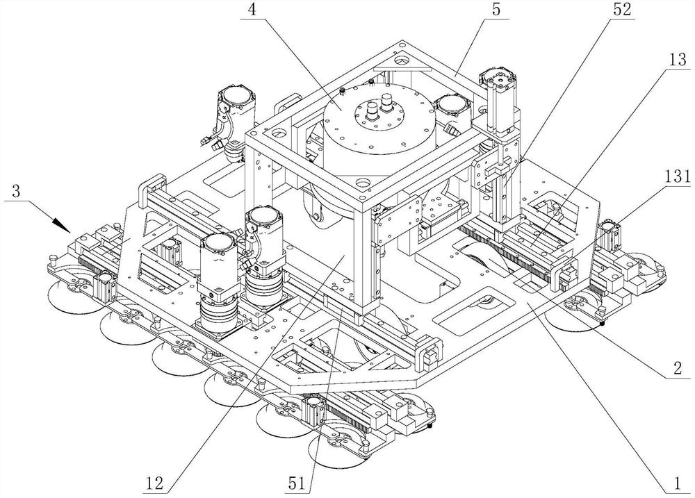
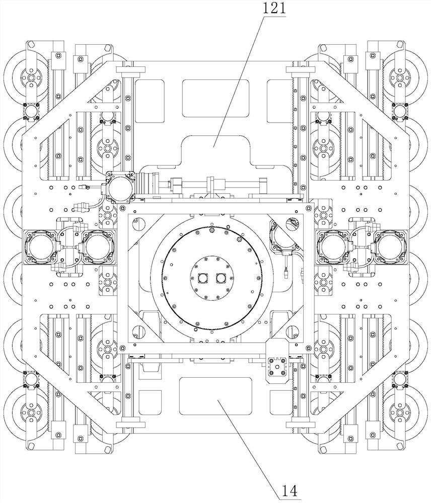
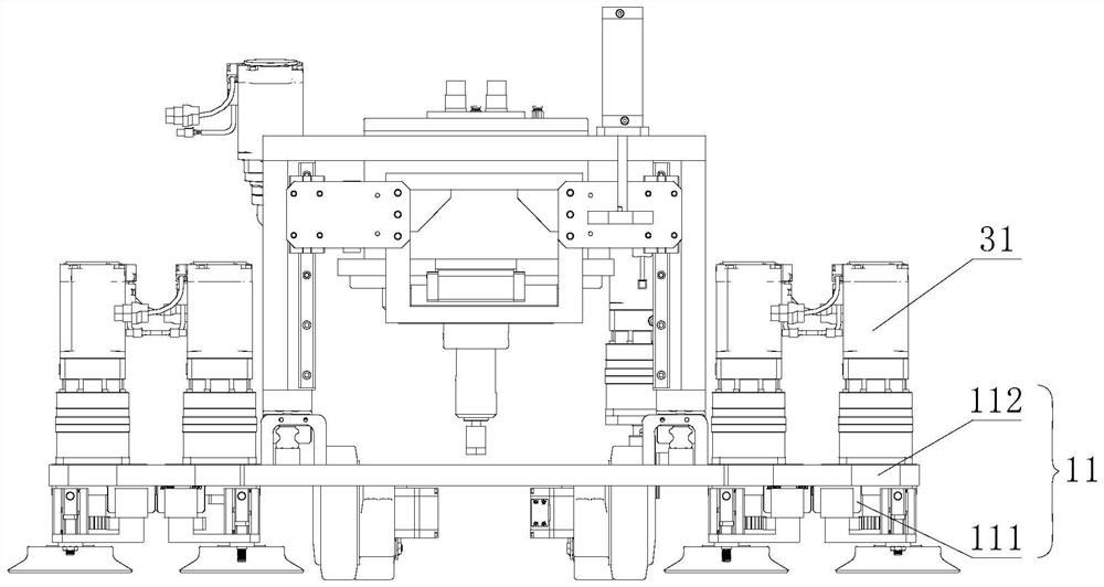
[0023] Such as Figure 1 to Figure 4 As shown, the mobile friction stir welding frame of this embodiment includes: a load frame 1, the load frame 1 is provided with two pairs of rollers 2 and two sets of installation positions 11 for connecting the crawler 3, the rollers 2 and the installation positions 11 are distributed symmetrically along the welding direction; the top surface of the carrying frame 1 is slidably installed along the welding direction with an execution frame 5 for installing the welding machine 4 .

[0024] The execution frame 5 that can slide along the welding direction is installed on the top surface of the carrying frame 1, and the welding machine 4 is installed in the execution frame 5. By the sliding of the execution frame 5, the welding machine 4 moves along the welding direction. When the execution frame 5 ca...


PUM


Abstract

The invention discloses a movable friction stir welding machine frame. The movable friction stir welding machine frame comprises a bearing machine frame, two pairs of rolling wheels and two sets of crawl devices are installed on the bottom face of the bearing machine frame, the crawl devices alternately move in the welding direction, and an execution machine frame used for installing a welding machine is installed on the top face of the bearing machine frame in the welding direction in a sliding mode. The execution machine frame capable of sliding in the welding direction is installed on the top face of the bearing machine frame, the welding machine is installed in the execution machine frame, and the welding machine moves along with the execution machine frame in the welding direction through sliding of the execution machine frame, and when the executing machine frame carries the welding machine to slide to the edge of the to-be-welded part, the welding machine can carry out welding operation on the end part of the to-be-welded part. According to welding equipment in the prior art, due to the fact that a welding machine is fixed to the middle of a machine frame and cannot move, welding can not be carried out on the edge of the to-be-welded part, and compared with the prior art, the movable friction stir welding machine frame can prolong the movement stroke of the welding machine to the edge position of the to-be-welded part, and uninterrupted welding in the whole process is achieved through cooperation of the execution machine frame and the crawl devices.

Description

technical field [0001] The invention mainly relates to the technical field of friction stir welding, in particular to a mobile friction stir welding frame. Background technique [0002] Friction stir welding uses the heat generated by the friction between the high-speed rotating welding tool and the workpiece to partially melt the material to be welded, and moves along the gap to be welded through the welding tool, and the plasticized material is passed by the front of the welding tool under the action of the rotating friction of the welding tool. The part flows to the rear and forms a dense solid-phase weld under the extrusion of the welding tool. This welding technology has the advantages of no spatter, no smoke, no porosity, no slag inclusion, no need for filling materials and shielding gas, low energy consumption, no pollution to the environment, etc., and has broad application prospects. [0003] In order to achieve continuous mobile welding, the frame equipped with th...

Claims


Application Information

Patent Timeline
Patent Type & Authority Applications(China)
IPC IPC(8): B23K20/12B23K20/26
CPCB23K20/1245B23K20/26
Inventor 雷智斌蒋习均黄韬苏俊伟
Owner 湖南智能焊接研究院有限公司
Why Eureka
Try Eureka