
Automatic laser welding machine for edge grinding wheel

A technology of laser welding machine and edging wheel, which is applied in the direction of laser welding equipment, welding equipment, metal processing equipment, etc., can solve the problems of ineffective control of welding path, backward welding process, low degree of automation, etc., and achieve automatic operation , Guarantee welding quality and reduce labor intensity

Pending Publication Date: 2022-04-15
郑州金海威科技实业有限公司
View PDF0 Cites 0 Cited by
  • Summary
  • Abstract
  • Description
  • Claims
  • Application Information

AI Technical Summary

Problems solved by technology

[0002] The edging wheel is mainly connected by welding the substrate and the cutter head. The edging wheel is mainly used for cutting and polishing of stone or other non-metallic materials. The cutter heads are generally arranged in a ring on the substrate. The substrate and the knife in the current technology The group-to-welding process of the head is relatively backward and the degree of automation is low. Not only there are operational errors in the arrangement of the substrate and the cutter head, but also the welding path cannot be effectively controlled during welding, which leads to problems in welding quality and affects the quality of the product.

Method used


Image

  • Automatic laser welding machine for edge grinding wheel
  • Automatic laser welding machine for edge grinding wheel
  • Automatic laser welding machine for edge grinding wheel

Examples


Embodiment Construction

[0098] The following will clearly and completely describe the exemplary schemes of the embodiments of the present invention with reference to the accompanying drawings of the specific embodiments of the present invention. Unless otherwise defined, the technical terms or scientific terms used in the present invention shall have the usual meanings understood by those skilled in the art.

[0099] In the description of the present invention, it should be understood that the expressions "first" and "second" are used to describe each element of the present invention, and do not represent any order, quantity or importance limitation, but are only used to describe One component is distinguished from another.

[0100] It should be noted that when an element is "connected", "coupled" or "connected" to another element, it may mean that it is directly connected, coupled or connected, but it should be understood that there may be Intermediate elements; that is, positional relationships co...


PUM


Abstract

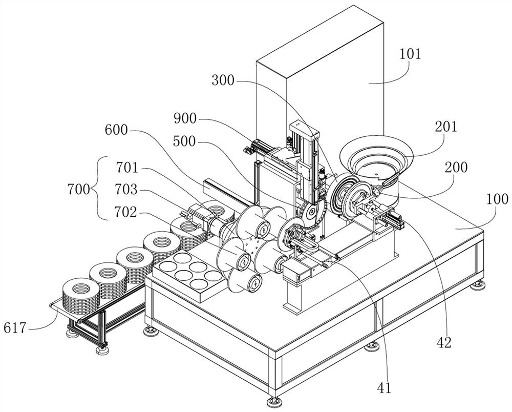
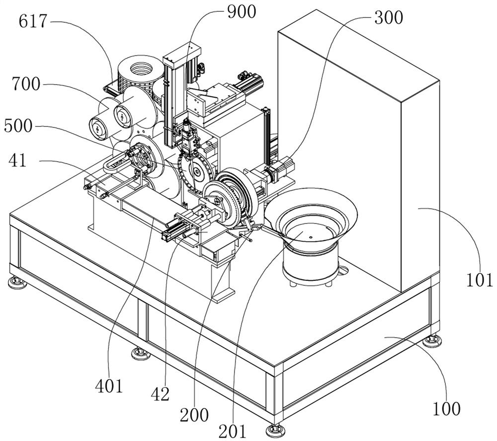
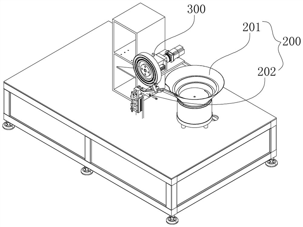
The invention belongs to the technical field of edge grinding wheel production. An edge grinding wheel automatic laser welding machine comprises a machine frame, a base body storage frame, a vibration disc, a tool bit arranging and clamping device, an edge grinding wheel welding rotating device, a base body taking and placing device, a tool bit taking and placing device, a laser welding device and an edge grinding wheel discharging and conveying device, and the base body storage frame is used for storing a base body; a tool bit feeding device is arranged at an outlet of the vibration disc; the tool bit arranging and clamping device is used for clamping the tool bits pushed out by the tool bit feeding device and arranging the tool bits annularly at intervals. The edge grinding wheel welding rotating device is used for clamping the base body and driving the base body to rotate. The base body taking and placing device grabs a base body and feeds the base body to the edge grinding wheel welding rotating device. The tool bit taking and placing device is used for grabbing a whole tool bit and aligning the base body. The laser welding device is used for welding the tool bit and the base body. The base body can be automatically grabbed and fed, and tool bits can be effectively arranged and integrally clamped and transferred, so that the tool bits and the base body are integrally aligned and welded.

Description

technical field [0001] The invention belongs to the technical field of edging wheel production, and in particular relates to an automatic laser welding machine for edging wheels. Background technique [0002] The edging wheel is mainly connected by welding the substrate and the cutter head. The edging wheel is mainly used for cutting and polishing of stone or other non-metallic materials. The cutter heads are generally arranged in a ring on the substrate. The substrate and the knife in the current technology The group-to-welding process of the head is relatively backward and the degree of automation is low. Not only there are operational errors in the arrangement of the substrate and the cutter head, but also the welding path cannot be effectively controlled during welding, which leads to problems in welding quality and affects the quality of the product. . In the processes of clamping, alignment and welding of the cutter head and the substrate, how to realize automation an...

Claims


Application Information

Patent Timeline
Patent Type & Authority Applications(China)
IPC IPC(8): B23K26/21B23K26/70
CPCB23K26/21B23K26/702
Inventor 吴志峰耿泽中于化龙贾文轩王志海
Owner 郑州金海威科技实业有限公司
Learn More