Novel welding device for producing capacitors

A technology for welding devices and capacitors, which is applied in the direction of capacitors, capacitor manufacturing, auxiliary devices, etc., and can solve the problems of manpower consumption and low efficiency

Inactive Publication Date: 2020-10-20
铜陵市凯瑞特电子有限公司
View PDF7 Cites 0 Cited by
  • Summary
  • Abstract
  • Description
  • Claims
  • Application Information

AI Technical Summary

Problems solved by technology

[0005] The purpose of the present invention is to solve the problem of labor-intensive and low efficiency in the prior art, and propose a new type of welding device for capacitor production

Method used


Image

  • Novel welding device for producing capacitors
  • Novel welding device for producing capacitors
  • Novel welding device for producing capacitors

Examples


Embodiment 1

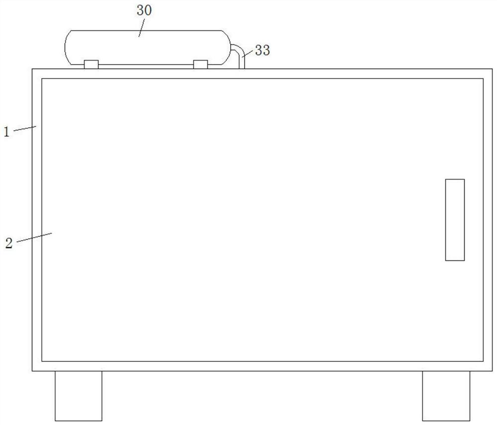
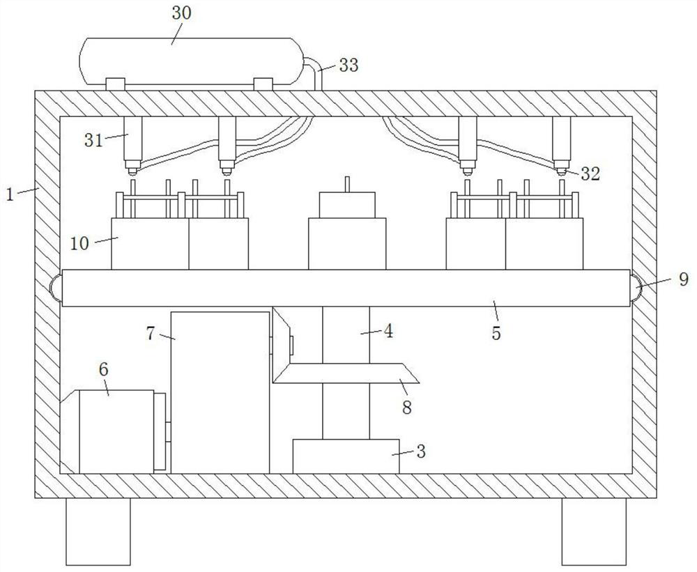
[0030] refer to Figure 1-6 , a new type of welding device for capacitor production, including a processing box 1, the front end of the processing box 1 is connected with a door 2 through hinge rotation, a mounting block 3 is fixed in the middle of the inner bottom of the processing box 1, and the upper end of the mounting block 3 The mounting rod 4 is connected to the rotating bearing through the rolling bearing. The top of the mounting rod 4 is fixed with a holding plate 5. The inner wall of one side of the processing box 1 is also fixed with a servo motor 6. One side of the servo motor 6 is provided with a reducer 7. The output of the servo motor 6 is The end is fixedly connected to the input end of the reducer 7, the output end of the reducer 7 is connected to the installation rod 4 through a bevel gear set 8, the side wall of the holding plate 5 is also equipped with a ball 9, and the inner wall of the processing box 1 There is also a rolling groove in the middle, and the...

Embodiment 2

[0033] Such as Figure 4 and 5 As shown, this embodiment is basically the same as Embodiment 1. Preferably, a bar-shaped groove 27 is provided on the top surface of the support plate 17, and the bar-shaped groove 27 communicates with the chute, and the upper end of the slider 18 is also fixed with a fixed rod 28 , the fixed rod 28 is slidably connected in the bar-shaped groove 27, and the upper end of the fixed rod 28 extends to the outer wall of the support plate 17 and is screwed to the limit block 29.

[0034] In this embodiment, a fixed rod 28 is fixed on the upper end of the slider 18, and a limit block 29 is fixed on the upper part of the fixed rod 28, so as to realize the temporary fixation of the slider 18, thereby ensuring that the temporary fixation of the capacitor is more stable, which is very good. It guarantees the quality of capacitor welding.

Embodiment 3

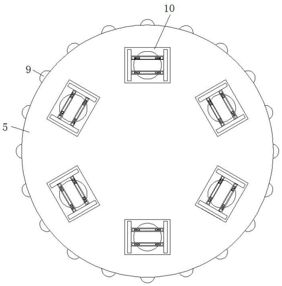
[0036] Such as figure 2 and 3 As shown, this embodiment is basically the same as Embodiment 1. Preferably, multiple balls 9 are provided and evenly distributed on the side wall of the holding plate 5 .

[0037] In this embodiment, a plurality of balls 9 are arranged on the side wall of the containing plate 5, so that the rotating of the containing plate 5 is more stable.


PUM


Abstract

The invention discloses a novel welding device for producing capacitors. The novel welding device comprises a machining box body. A door body is connected to one side of the front end of the machiningbox body in a rotary manner through hinges. A mounting block is fixed to the middle of the bottom face inside the machining box body. A mounting rod is connected to the upper end of the mounting block in a rotary manner through a rolling bearing. A containing plate is fixed to the top end of the mounting rod. A servo motor is further fixed to the inner wall of one side of the machining box. A reducer is arranged at one side of the servo motor. The output end of the servo motor is fixedly connected to the input end of the reducer. The output end of the reducer is connected with the mounting rod through a bevel gear set in a rotary manner. The side wall of the containing plate is provided with rolling balls. A rolling groove is formed in the middle of the inner wall of the machining box body. All the rolling balls are arranged in the rolling groove. The novel welding device is reasonable in design and great in innovation; the capacitor welding automation degree is high; the work requirement of mass production of the capacitors is well met; and the capacitor welding efficiency is greatly improved.

Description

technical field [0001] The invention relates to the technical field of capacitor production equipment, in particular to a novel welding device for capacitor production. Background technique [0002] A capacitor is mainly a device used to hold charges, and it is one of the electronic components used in large quantities in electronic equipment. During the processing and production of capacitors, auxiliary welding devices are required for welding work. [0003] After retrieval, the patent with application number 201920937753.3 discloses an auxiliary welding device for capacitor production, including a base, balls and a second gear. A first gear is installed inside the left end of the base, and the first gear is connected to the base through balls. The top surface of a gear is provided with a rotating rod, and the rotating rod passes through the base, the second gear is meshed and connected to the right side of the first gear, and the center of the top surface of the second gear...

Claims


Application Information

Patent Timeline
IPC IPC(8): B23K31/02B23K37/00B23K37/02B23K37/04H01G13/00
CPCB23K31/02B23K37/00B23K37/02B23K37/0435H01G13/00
Inventor 陶龙喧陈学贵
Owner 铜陵市凯瑞特电子有限公司
Why Eureka
Try Eureka