Method for winding a concentrated coil for an electric machine

A coil and coil winding technology, applied in the field of coils wound according to this method, winding coils used in motors, can solve the problem that the result is not optimal, etc., and achieve the effect of high slot filling factor

Pending Publication Date: 2021-10-26
康士伯海事股份有限公司
View PDF6 Cites 0 Cited by
  • Summary
  • Abstract
  • Description
  • Claims
  • Application Information

AI Technical Summary

Problems solved by technology

However, the results of this process are not optimal, as some turns of the coil stick out, or the end wire bends to lead out of the center of the coil

Method used


Image

  • Method for winding a concentrated coil for an electric machine
  • Method for winding a concentrated coil for an electric machine
  • Method for winding a concentrated coil for an electric machine

Examples


Embodiment Construction

[0051] Various aspects of the disclosure are described more fully hereinafter with reference to the accompanying drawings. This disclosure may, however, be embodied in many different forms and should not be construed as limited to any specific structure or function presented throughout this disclosure. Rather, these aspects are provided so that this disclosure will be thorough and complete, and will fully convey the scope of the disclosure to those skilled in the art. Based on the teachings herein, those skilled in the art should appreciate that the scope of the present disclosure is intended to encompass any aspect disclosed herein, whether implemented independently of or in combination with any other aspect of the present disclosure. For example, an apparatus may be implemented or a method may be practiced using any number of aspects set forth herein. Furthermore, the scope of the disclosure is intended to cover apparatus or methods practiced with other structure, functiona...


PUM


Abstract

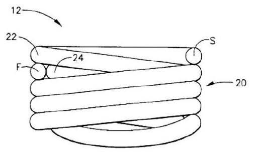
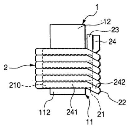
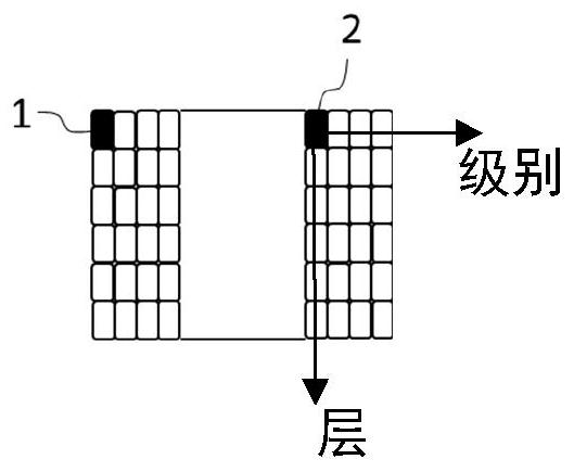
A method for winding a coil for electric machines, and a coil wound according to this method. The method comprises the following steps: placing a wire against a form, leaving a first length of the wire and a second length of the wire extending from the form, wherein the first length has a first end and the second length has a second end; winding the first length in a first direction round the form, such that the first end of the first length is ending in an outer layer of the plurality of layers; winding the second length in a second direction round the form, wherein the second direction is opposite the first direction, wherein the second end of the second length is ending in an outer layer of the plurality of layers, wherein all layers and levels of the coil are filled.

Description

technical field [0001] The present invention relates generally to coil winding, and more particularly to a method for winding a coil for an electric motor, and a coil wound according to the method. Background technique [0002] Problems with prior art [0003] Concentrated coils are used for the winding of a fairly wide range of types of motors. A well designed motor is usually characterized by a high slot fill factor providing high thermal conductivity within the slot, which improves heat dissipation from the conductors to the core. A high slot fill factor can be achieved when there is little insulation, impregnation material or air between the conductors in the slot and no coil turns protrude laterally. For many machines, the best shape for the coil is a rectangular or parallelogram shape to follow the shape of the slot and allow the coil to be inserted into the slot. [0004] In order to make a strong reinforcing coil, one usually uses a form on which the coil is wound...

Claims


Application Information

Patent Timeline
Patent Type & Authority Applications(China)
IPC IPC(8): H02K3/04H02K15/04
CPCH02K3/04H02K15/045H02K2213/03H02K15/095
Inventor E·勒夫利
Owner 康士伯海事股份有限公司
Why Eureka
Try Eureka