headlight control unit

A technology for control devices and headlights, which is applied in printing devices, signal devices, projection devices, etc., and can solve problems such as difficult to recognize images

Active Publication Date: 2018-12-21
DENSO CORP
View PDF1 Cites 0 Cited by
  • Summary
  • Abstract
  • Description
  • Claims
  • Application Information

AI Technical Summary

Problems solved by technology

Therefore, even if you want to project the same image at the same position on the road surface through a pair of headlamps, the image projected on the road surface by the light of one headlamp will be different from the image projected on the road surface by the light of the other headlamp. The projected image is biased and it is difficult to recognize the image

Method used


Image

  • headlight control unit
  • headlight control unit
  • headlight control unit

Examples


no. 1 approach >

[0018] 1. Structure of the headlight control device 1 and the headlight device 7

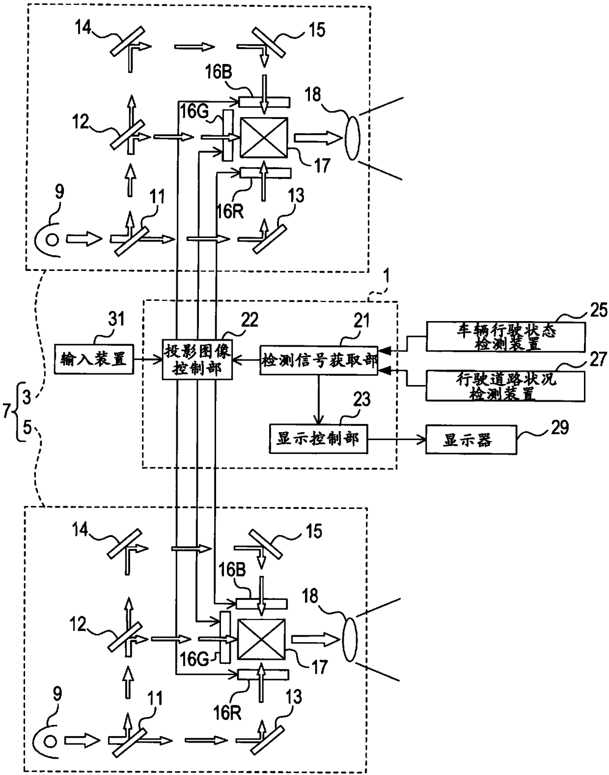
[0019] based on figure 1 The structure of the headlight control device 1 and the headlight device 7 will be described. The headlight control device 1 is an in-vehicle device that controls a headlight device 7 including a pair of headlight units 3 and 5.

[0020] The headlight unit 3 is arranged at a left position of the front end of the vehicle, and the headlight unit 5 is arranged at a right position of the front end of the vehicle. The headlight units 3 and 5 irradiate light toward the front of the vehicle, respectively. The headlight units 3 and 5 have the same structure. Here, the headlight unit 3 will be described as an example.

[0021] The headlight unit 3 includes a light source 9. As the light source 9, various known lamps that can be used as a light source for a headlight of a vehicle, such as a halogen lamp and a xenon lamp, can be used. The light source 9 is controlled by the headlight...

no. 2 approach >

[0054] 1. Structure of the headlight control device 1 and the headlight device 7

[0055] The structures of the headlight control device 1 and the headlight device 7 are basically the same as those of the first embodiment described above, and are partially different. Hereinafter, the description will focus on the differences.

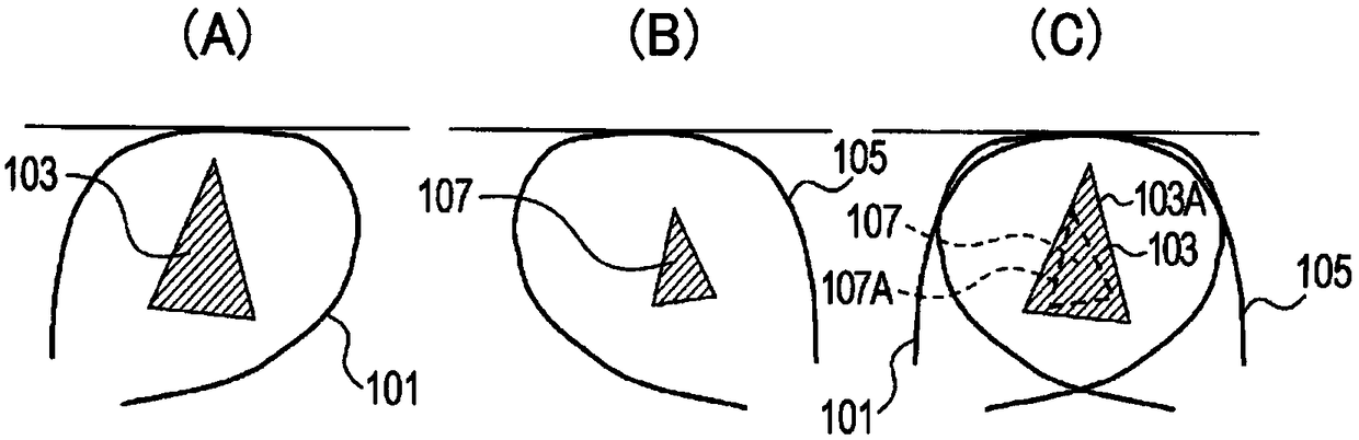
[0056] When the projection image control section 22 uses the headlight units 3 and 5 to project a composite image of a specific shape on the road surface, the liquid crystal panels 16R, 16G, 16B of the headlight unit 3 and the liquid crystal panels of the headlight unit 5 are 16R, 16G, and 16B generate mutually different images.

[0057] That is, the projection image control unit 22 generates images of a specific shape in large sizes on the liquid crystal panels 16R, 16G, and 16B of the headlight unit 3. The result is such as image 3 As shown in (A), in the synthetic light 101 irradiated from the headlight unit 3, an image 109 of a specific shape is project...

no. 3 approach >

[0065] 1. Structure of the headlight control device 1 and the headlight device 7

[0066] The structures of the headlight control device 1 and the headlight device 7 are basically the same as those of the first embodiment described above, but some are different. Hereinafter, the description will focus on the differences.

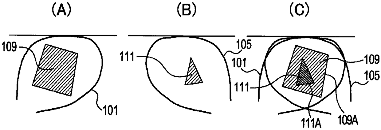
[0067] When the projection image control unit 22 uses the headlight units 3 and 5 to project a composite image of a specific shape on the road surface, the liquid crystal panels 16R, 16G, and 16B of the headlight unit 3 do not generate images, and the headlight unit 3 The liquid crystal panels 16R, 16G, and 16B of 5 generate images.

[0068] That is, the projection image control section 22 does not generate images on the liquid crystal panels 16R, 16G, and 16B of the headlight unit 3, such as Figure 4 As shown in (A), the brightness of the synthesized light 101 irradiated from the headlight unit 3 is increased at any position.

[0069] On the other hand, the proj...


PUM


Abstract

A headlight control apparatus (1) for performing control on a headlight device (7) which includes a pair of headlight units (3, 5) each including a light source (9) and an image forming section (16R, 16G, 16B) capable of forming an image and disposed in a light path of light from the light source to illuminate light (101, 105) for projecting the image onto a road surface, wherein the headlight control apparatus forms the image in the image forming section such that a first image (103) projected onto the road surface by one of the headlight units includes a second image (107) projected onto the road surface by the other headlight unit.

Description

Technical field [0001] The invention relates to a headlamp control device. Background technique [0002] As a headlight device of a vehicle, a headlight device in the form of a projector is known. A headlamp device in the form of a projector is provided, for example, on a liquid crystal panel capable of forming an image through the optical path of light from a light source, and the light transmitted through the liquid crystal panel is projected onto the road surface in front of the vehicle via a lens. As a result, the image formed on the liquid crystal panel is projected on the road surface (refer to Patent Document 1). [0003] Patent Document 1: Japanese Patent Application Publication No. 2008-143505 [0004] Since a vehicle usually has a pair of left and right headlamps, it is considered that the light passing through both headlamps project the same image at the same position on the road surface. However, the image projected on the road surface is stretched in a specific direct...

Claims


Application Information

Patent Timeline
Patent Type & Authority Patents(China)
IPC IPC(8): B60Q1/04
CPCB60Q1/143B60Q2300/112B60Q2300/114B60Q2300/132B60Q2300/312B60Q2300/322B60Q2300/324B60Q2300/45B60Q2400/50F21S41/162F21S41/172F21S41/25F21S41/285F21S41/645G03B21/006G03B29/00B60Q1/16B60Q2300/054
Inventor 水野龙
Owner DENSO CORP
Why Eureka
Try Eureka