
Assembly type corrugated steel web cantilever prefabricated assembled bridge structure and construction method

A corrugated steel web, prefabricated assembly technology, applied in the direction of erecting/assembling bridges, bridges, bridge parts, etc., can solve the problems of low construction accuracy, difficulty in convenient adjustment of mutual positions, and easy cracking of the connecting structure. Achieve the effect of convenient hoisting operation, high positioning efficiency and improved integrity

Active Publication Date: 2021-10-29
JSTI GRP CO LTD +1
View PDF7 Cites 2 Cited by
  • Summary
  • Abstract
  • Description
  • Claims
  • Application Information

AI Technical Summary

Problems solved by technology

However, the cast-in-place construction method of the traditional cantilever technology is difficult to achieve convenient adjustment of the mutual position in the butt assembly of the prefabricated floor and the corrugated I-beam, resulting in low construction accuracy during the hoisting and assembling process, and the traditional assembly structure in the corrugated Problems such as cracking are prone to occur in the connection structure between I-beam and prefabricated roof and prefabricated bottom slab

Method used


Image

  • Assembly type corrugated steel web cantilever prefabricated assembled bridge structure and construction method
  • Assembly type corrugated steel web cantilever prefabricated assembled bridge structure and construction method
  • Assembly type corrugated steel web cantilever prefabricated assembled bridge structure and construction method

Examples


Embodiment Construction

[0055] The present invention will be further described below in conjunction with the accompanying drawings. The following examples are only used to illustrate the technical solution of the present invention more clearly, but not to limit the protection scope of the present invention.

[0056] In describing the present invention, it should be understood that the terms "center", "longitudinal", "transverse", "upper", "lower", "front", "rear", "left", "right", " The orientations or positional relationships indicated by "vertical", "horizontal", "top", "bottom", "inner" and "outer" are based on the orientations or positional relationships shown in the drawings, and are only for the convenience of describing the present invention and Simplified descriptions, rather than indicating or implying that the device or element referred to must have a particular orientation, be constructed and operate in a particular orientation, and thus should not be construed as limiting the invention. ...


PUM


Abstract

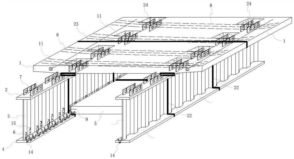
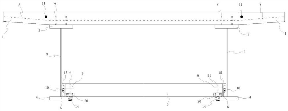
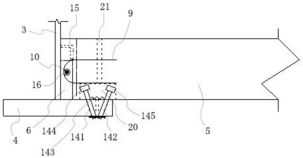
The invention discloses an assembly type corrugated steel web cantilever prefabricated assembly bridge structure and a construction method, and belongs to the technical field of bridge engineering construction.The assembly structure comprises corrugated I-shaped steel, a prefabricated top plate, an upper flange steel plate fixedly arranged on the top of the corrugated I-shaped steel, and a prefabricated bottom plate; the prefabricated top plate is fixedly arranged on a lower flange steel plate at the bottom of the corrugated I-shaped steel; the prefabricated bottom plate is close to the side end and is positioned and connected to the lower flange steel plate through a plurality of self-adjusting connecting pieces in the longitudinal direction, and a concrete pouring gap is formed between the side end of the prefabricated bottom plate and the corrugated I-shaped steel. In a concrete pouring gap, the corrugated I-shaped steel is fixedly provided with a plurality of outer wrapping connecting pieces provided with first through holes in the longitudinal direction, the side end of the prefabricated bottom plate is fixedly provided with a plurality of U-shaped steel bars in the longitudinal direction, and the U-shaped steel bars and the first through holes are arranged in a staggered mode in the longitudinal direction and are arranged on the same longitudinal steel bar in a penetrating and sleeving mode. According to the splicing structure, the bridge and the method, the structural integrity, the construction efficiency and the construction precision are improved.

Description

technical field [0001] The invention belongs to the technical field of bridge engineering construction, and in particular relates to an assembled corrugated steel web cantilever prefabricated assembled bridge structure and a construction method. Background technique [0002] The corrugated steel web composite bridge is a steel-concrete composite structure. Compared with traditional concrete girder bridges, corrugated steel web composite girder bridges have the advantages of light weight, convenient construction, beautiful appearance, etc., and avoid common problems such as web cracking in ordinary concrete girder bridges, and have broad engineering application prospects. [0003] In recent years, bridges with corrugated steel webs have been gradually increasing in span, and cantilever technology is mostly used in the construction of long-span bridges. However, the cast-in-place construction method of the traditional cantilever technology is difficult to achieve convenient a...

Claims


Application Information

Patent Timeline
Patent Type & Authority Applications(China)
IPC IPC(8): E01D19/00E01D21/00E01D21/10
CPCE01D19/00E01D21/00E01D21/10
Inventor 刘朵邓文琴黄健张建东侯爵查上张爱军赵俊明龙凌宇杨红成
Owner JSTI GRP CO LTD
Learn More