Supercharge Your Innovation With Domain-Expert AI Agents!

Drilling installation; Handling system, method for independent operations.

A handling system and drilling technology, which is applied to drilling equipment, supporting devices, drilling pipes, etc., and can solve problems such as high cost rates

Pending Publication Date: 2021-10-29
GUSTOMSC BV
View PDF0 Cites 2 Cited by
  • Summary
  • Abstract
  • Description
  • Claims
  • Application Information

AI Technical Summary

Problems solved by technology

[0009] Due to the high cost rate of drilling rigs and dangerous operations on the rig floor, there are constant challenges in improving the operational efficiency of drilling rigs and providing a relatively safe working environment

Method used


Image

  • Drilling installation; Handling system, method for independent operations.
  • Drilling installation; Handling system, method for independent operations.
  • Drilling installation; Handling system, method for independent operations.

Examples


Embodiment Construction

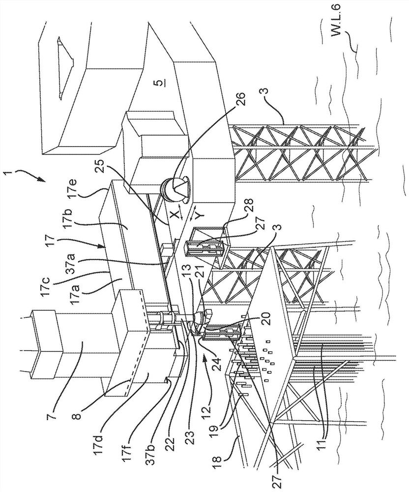
[0067] figure 1 A schematic perspective view of the drilling device 1 is shown. Here, the drilling device 1 is implemented as a jack-up platform. Such drilling rigs 1 are usually placed temporarily at offshore locations next to well platforms 18 producing oil and / or gas fields. The drilling device 1 may be used for drilling wells when exploring oil and / or gas fields, and may be used for well maintenance or repair and / or for well intervention during well production.

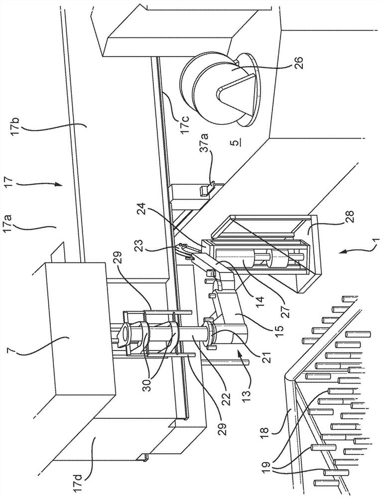
[0068] figure 1 A schematic perspective view of a drilling arrangement 1 comprising a cantilever beam 17 is shown. Here, the mast 7 is positioned above the cantilever beam 17 . The drill floor 8 is located at the upper side 17 a of the outrigger beam 17 . The cantilever beam 17 also has a lateral side 17b, a lateral side 17c, a rear side 17d, a front side 17e and a bottom side 17f.

[0069] A moon pool 10 (not visible in the figure) is provided through the opening of the cantilever beam 17 through which the ...


PUM


Abstract

Drilling installation comprising a cantilever with a derrick and a drilling floor for performing drilling operations; further comprising an independent operations handling system arranged for handling equipment underneath the drilling floor independent of the drilling operations on the drilling floor, wherein the independent operations handling system comprises a handling element for cooperation with the equipment to be handled, wherein the handling element is movable in a XY-plane underneath the cantilever.

Description

technical field [0001] The present invention relates to drilling equipment. Background technique [0002] Well drilling rigs are known for drilling water, oil and / or natural gas wells in onshore or offshore locations. The drilling unit may be a mobile unit, such as a mobile offshore jack-up rig, or may be a mobile unit mounted on a truck. Drilling rigs may also be of a more stationary character, such as a fixed land-based structure, or a fixed offshore-based structure such as a drilling platform. Offshore drilling rigs may generally be referred to as drilling rigs. Accordingly, the terms drilling rig and drilling rig are used interchangeably. [0003] A drilling rig typically includes a drill floor. The drill floor is the layer on which the drilling rig operates during drilling operations. The drill floor is generally the layer that handles and connects the tubulars or drill string used to drill the well. The drill floor includes the hole through which the drill string...

Claims


Application Information

Patent Timeline
IPC IPC(8): E21B15/00E21B15/02E21B19/22E02B17/02
CPCE02B17/021E21B15/003E21B15/02E21B19/22E02B2017/006E21B19/008
Inventor 约瑟夫·莱昂纳德斯·阿洛伊修斯·玛丽亚·范德霍恩张纳新马克·科尼利厄斯·马里纳斯·弗朗西斯科·罗门斯霍弗特·亨德里克·特尼斯·泽德沃尔德
Owner GUSTOMSC BV
Features
  • R&D
  • Intellectual Property
  • Life Sciences
  • Materials
  • Tech Scout
  • Unparalleled Data Quality
  • Higher Quality Content
  • 60% Fewer Hallucinations
Learn More