Electric power distribution panel

A power distribution and power supply technology, which is applied to substations/switchgear boards/panels/desks, etc., can solve the problems of low application flexibility and supply voltage

Pending Publication Date: 2021-10-29
DELTA ELECTRONICS INC
View PDF0 Cites 0 Cited by
  • Summary
  • Abstract
  • Description
  • Claims
  • Application Information

AI Technical Summary

Problems solved by technology

[0003] However, in the case that the above-mentioned input buses are all connected to the same input power source, multiple loads can only receive the same voltage from the power distribution panel, that is, it is impossible to provide corresponding voltages according to the actual needs of different loads, and application flexibility lower

Method used


Image

  • Electric power distribution panel
  • Electric power distribution panel
  • Electric power distribution panel

Examples


Embodiment Construction

[0045] Some typical embodiments embodying the features and advantages of the present invention will be described in detail in the description in the following paragraphs. It should be understood that the invention is capable of various changes in different aspects without departing from the scope of the invention, and that the description and illustrations therein are illustrative in nature and not limiting. this invention.

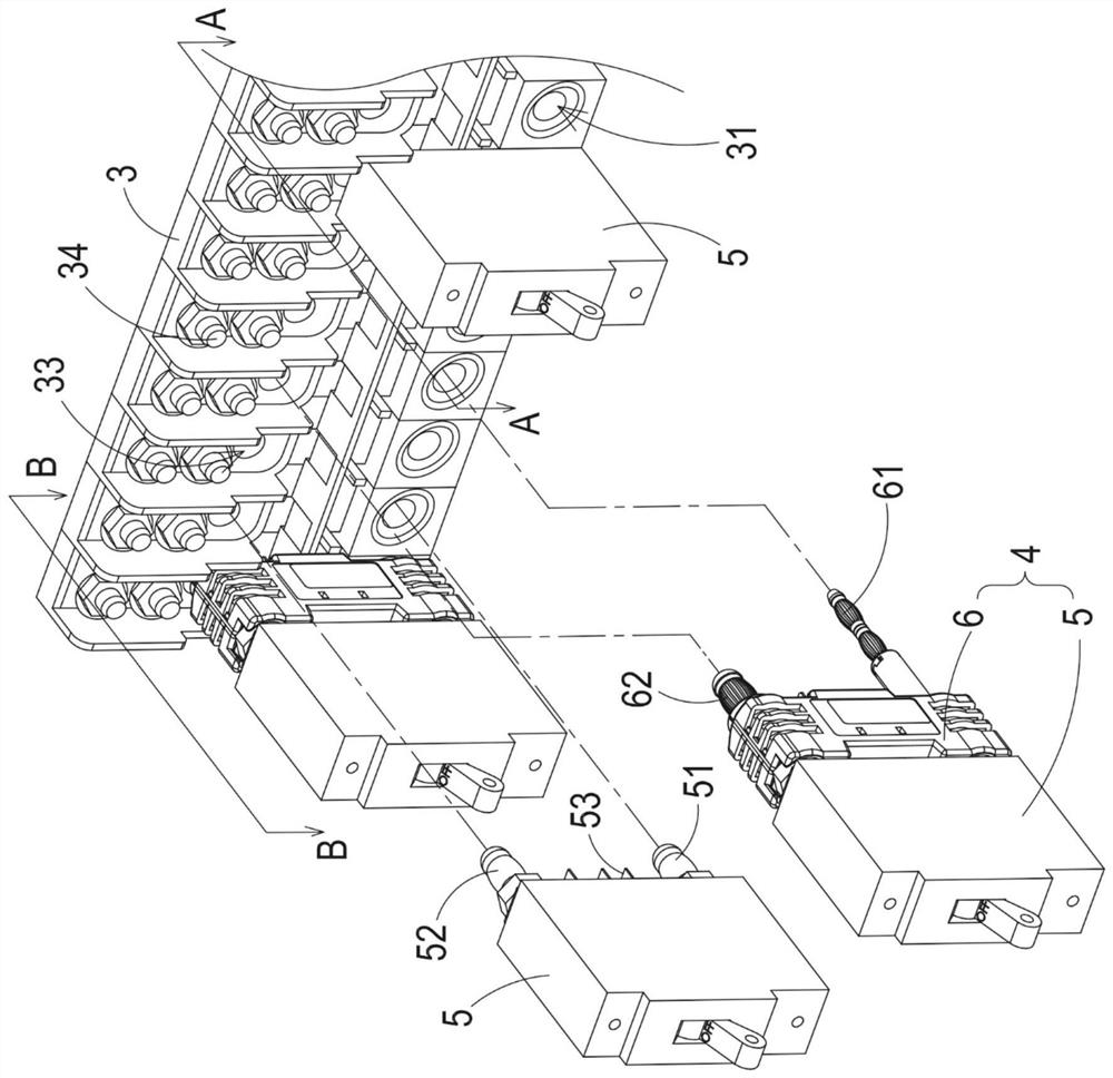
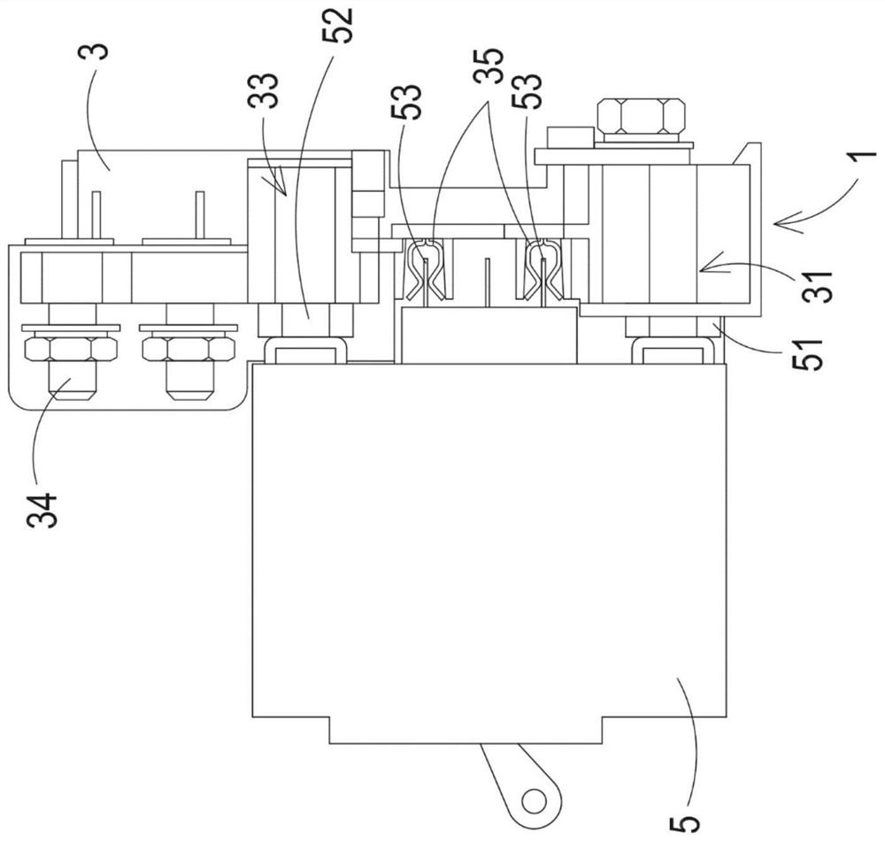
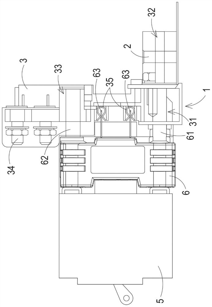
[0046] figure 1 It is a three-dimensional structure schematic diagram of a power distribution panel in a preferred embodiment of the present invention. Figure 2A and Figure 2B are respectively figure 1 Schematic cross-sectional views of the power distribution panel along sections AA and BB. Such as figure 1 , Figure 2A and Figure 2B As shown, the power distribution board includes a first input bus 1 , a second input bus 2 , multiple brackets 3 and multiple circuit breaker modules 4 . The first input bus 1 and the second input bus 2 are respect...


PUM


Abstract

An electric power distribution panel is provided. The electric power distribution panel includes a first input bus, a second input bus, a plurality of brackets and a plurality of circuit breaker modules. The first and second input buses are coupled to a first power source and a second power source respectively. The plurality of brackets is electrically connected to the first and second input buses. The plurality of circuit breaker modules are assembled to the plurality of brackets respectively. Each of the plurality of circuit breaker modules includes a circuit breaker and an adapter detachably assembled to the circuit breaker. In each of the plurality of circuit breaker modules, the circuit breaker is electrically connected to the first input bus when the adapter is removed from the circuit breaker, and the circuit breaker is electrically connected to the second input bus when the adapter is assembled to the circuit breaker.

Description

technical field [0001] The invention relates to a power distribution board, especially a power distribution board with optional output voltage. Background technique [0002] Power distribution panels are widely used in power distribution systems, and their main purpose is to distribute power from input power to loads through circuit breakers. A power distribution panel typically contains a plurality of circuit breakers, and a plurality of brackets for mounting the aforementioned circuit breakers. Each bracket is electrically connected to the input bus, and the input bus is electrically connected to the same input power supply to provide a specific voltage to the circuit breaker assembled on the bracket. Under normal circumstances, after the circuit breaker is turned on, the electric energy received by it will be transmitted to the load. Once an over-current situation occurs, the circuit breaker will automatically disconnect to cut off the electrical connection path between...

Claims


Application Information

Patent Timeline
IPC IPC(8): H02B1/015
CPCH02B1/015
Inventor 余海强文森·马克·伯恩杨善淳
Owner DELTA ELECTRONICS INC
Why Eureka
Try Eureka