
Method for punching LED lamp holder

A technology for LED lamp holders and lamps, which is applied in the direction of boring/drilling, drilling/drilling equipment, parts of boring machines/drilling machines, etc. Labor intensity, the effect of improving production efficiency

Active Publication Date: 2021-11-02
安徽川越通信科技有限责任公司
View PDF6 Cites 1 Cited by
  • Summary
  • Abstract
  • Description
  • Claims
  • Application Information

AI Technical Summary

Problems solved by technology

In the traditional processing process, it mainly relies on manual alignment of each inclined processing surface for drilling. This operation method requires manual alignment of the processing surface many times. First, the efficiency of drilling is low, and second, the quality of drilling is difficult to guarantee.

Method used


Image

  • Method for punching LED lamp holder
  • Method for punching LED lamp holder
  • Method for punching LED lamp holder

Examples


Embodiment Construction

[0026] In order to make the objects and advantages of the present invention clearer, the present invention will be specifically described below in conjunction with examples. It should be understood that the following words are only used to describe one or several specific implementation modes of the present invention, and do not strictly limit the protection scope of the specific claims of the present invention. The existing structures not described in detail in the present invention are all implemented according to the existing technical solutions.

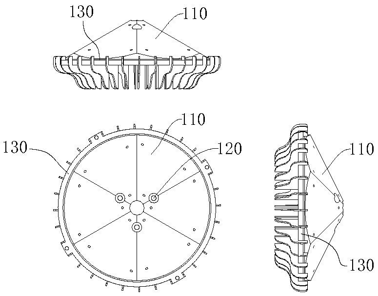
[0027] Such as figure 1 The shown LED lamp holder includes a lamp base 100 . The lamp base 100 has each processing surface 110 , three process holes 120 , and each heat sink, and each heat sink is assembled on a heat sink circular platform 130 .

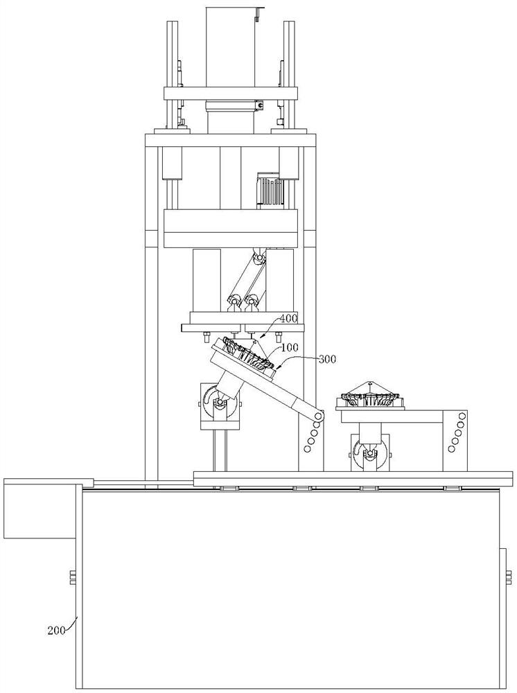
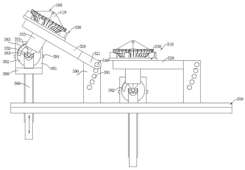
[0028] Such as figure 2 , 3 As shown in , 4 and 5, an automatic punching production equipment for LED lamp holders includes a frame 200, and the frame 200 is provided with a clampin...


PUM


Abstract

The invention relates to a method for punching an LED lamp holder. The method comprises the following steps on punching production equipment: a lamp base is assembled on a clamping structure A, at least one machining surface on the lamp base is horizontally arranged, a punching unit on the upper side of the horizontally arranged machining surface is adjusted to move downwards, the horizontally arranged machining surface is punched by the punching unit, the clamping structure A is adjusted to rotate around the center line of the clamping structure A after punching is finished, so that the other machining surface which is not punched on the clamping structure A is adjusted to be horizontally arranged and punched, the operation is repeated in this way until all the machining surfaces on the lamp base are punched, and then the lamp base is detached from the clamping mechanism A. According to the method, rapid and automatic punching operation on lamp bases of different sizes and models can be effectively realized, the production efficiency is improved, and the labor intensity is reduced.

Description

technical field [0001] The invention relates to the field of processing equipment for LED lamp holders, in particular to a method for punching holes in LED lamp holders. Background technique [0002] Such as figure 1 As shown, it is a schematic structural diagram of the base of the LED lamp. The base of the LED lamp has various processing surfaces, and three holes need to be opened on each processing surface, and each processing surface forms a cone-column-shaped edge. In the traditional processing process, it mainly relies on manual alignment of each inclined processing surface for drilling. This operation method requires manual alignment of the processing surface many times. First, the efficiency of drilling is low, and second, the quality of drilling is difficult to guarantee. . Therefore, it is necessary to provide a production device capable of automatically punching holes for the base of the LED lamp. Contents of the invention [0003] In order to solve the above ...

Claims


Application Information

Patent Timeline
Patent Type & Authority Applications(China)
IPC IPC(8): B23B41/00B23B47/00B23Q3/06H05B33/10
CPCB23B41/00B23B47/00B23Q3/06H05B33/10
Inventor 杨国顺
Owner 安徽川越通信科技有限责任公司
Learn More