Profile buckling structure shape follow-up positioning automatic welding machine

A technology of automatic welding machine and positioning mechanism, which is applied in welding equipment, auxiliary welding equipment, welding/cutting auxiliary equipment, etc., and can solve the problems of low efficiency of manual welding, inconsistency of welding wire molten pool center, straight line accuracy error, etc.

Active Publication Date: 2021-11-02
HENAN WEIHUA HEAVY MACHINE
View PDF9 Cites 0 Cited by
  • Summary
  • Abstract
  • Description
  • Claims
  • Application Information

AI Technical Summary

Problems solved by technology

[0003] Commonly used structures include direct buckle and intermediate splint. Since most of the profiles are supplied in a hot-rolled state, there are certain errors in the width of the flange and the accuracy of the straight line. After the profile is assembled, the width dimension and the straight line There is a certain deviation in the degree of welding. Since the center of the seam needs to be consistent with the center of the welding wire molten pool during welding, the welding path needs to be corrected in real time according to the position of the seam. Currently, the welding methods used are manual welding and rail-type trolley welding. In the two forms, manual welding is inefficient and labor-intensive; during the welding process of track-type trolley, trolley tracks need to be laid frequently, and the welding position cannot be corrected in real time, which may easily cause the center of the joint seam and the center of the welding wire molten pool to be inconsistent.

Method used


Image

  • Profile buckling structure shape follow-up positioning automatic welding machine
  • Profile buckling structure shape follow-up positioning automatic welding machine
  • Profile buckling structure shape follow-up positioning automatic welding machine

Examples


Embodiment Construction

[0021] The following will clearly and completely describe the technical solutions in the embodiments of the present invention with reference to the accompanying drawings in the embodiments of the present invention. Obviously, the described embodiments are only some, not all, embodiments of the present invention. Based on the embodiments of the present invention, all other embodiments obtained by persons of ordinary skill in the art without making creative efforts belong to the protection scope of the present invention.

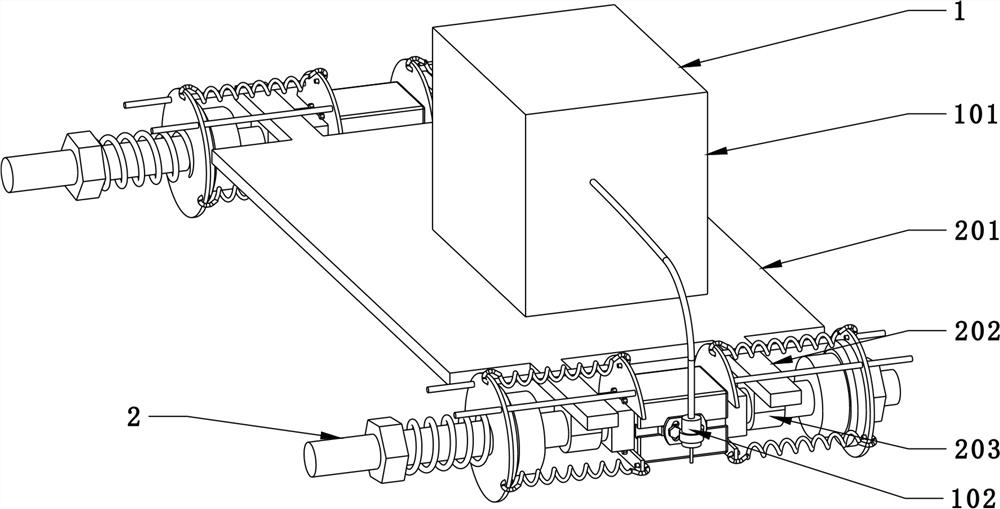
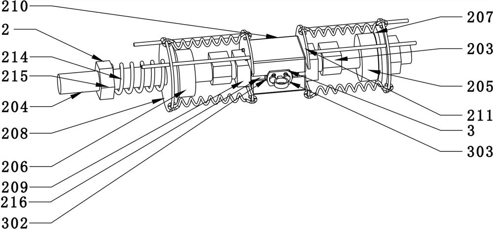
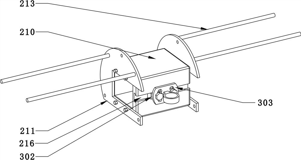
[0022] see Figure 1-5 , the present invention provides a technical solution: profile buckle structure conformal positioning automatic welding machine, including a welding mechanism 1 with a welding machine 101 and a welding torch 102, a displacement positioning mechanism 2 and a welding torch fixing mechanism 3; the displacement positioning mechanism 2 includes a support plate 201, connection plate 202, connection seat 203, welding machine 101 is installed on...


PUM


Abstract

The invention discloses a profile buckling structure shape follow-up positioning automatic welding machine. The profile buckling structure shape follow-up positioning automatic welding machine comprises a welding mechanism, a displacement positioning mechanism and a welding gun fixing mechanism, wherein the welding mechanism is provided with a welding machine and a welding gun; the displacement positioning mechanism comprises a supporting plate, a connecting plate and a connecting base, the welding machine is installed at the top of the supporting plate, horizontal supporting shafts are arranged at the two ends of the supporting plate, and one ends of shaft bodies of the supporting shafts are rotationally connected with fixed end wheels. According to the profile buckling structure shape follow-up positioning automatic welding machine, the displacement positioning mechanism of the welding machine is provided with a fixed wheel and a movable wheel, the movable wheel can be automatically moved and adjusted according to the tensile force of a tension spring to adapt to changes of the width and straightness of buckling profiles, the distance between the wheels is changed due to the size deviation of the profiles. The tension force of the tension spring causes a connecting sleeve to move slightly, and then the welding gun moves slightly along with the connecting sleeve, so that the purpose that the center of a splicing seam and the center of a welding wire molten pool are kept consistent all the time in the welding process is achieved.

Description

technical field [0001] The invention relates to the technical field of welding of structural parts, in particular to an automatic welding machine for conformal positioning of profile buckle structures. Background technique [0002] The profile butt welding form is a commonly used form of crane rod structure. This structure can weld two or more profiles of the same type (or different types) into one component. This structure is relatively different from the panel structure. , can effectively reduce the weight of structural parts, increase its mechanical performance, reduce welding deformation, and reduce production costs. [0003] Commonly used structures include direct buckle and intermediate splint. Since most of the profiles are supplied in a hot-rolled state, there are certain errors in the width of the flange and the accuracy of the straight line. After the profile is assembled, the width dimension and the straight line There is a certain deviation in the degree of weld...

Claims


Application Information

Patent Timeline
Patent Type & Authority Applications(China)
IPC IPC(8): B23K37/02B23K37/04
CPCB23K37/02B23K37/04
Inventor 吴庆富刘永刚李静宇李永福彭生韩艳红付晓辰刘峰杨彬李硕
Owner HENAN WEIHUA HEAVY MACHINE
Why Eureka
Try Eureka