Cutter grinding device capable of preventing cutting precision from being affected by uneven cutting edge
An uneven and high-precision technology, applied in the field of tool grinding devices, can solve problems such as increasing work efficiency, affecting the speed of grinding, and affecting the accuracy of cutting tools, so as to achieve the effects of accelerating work efficiency, saving working time, and facilitating the adjustment of grinding speed
- Summary
- Abstract
- Description
- Claims
- Application Information
AI Technical Summary
Problems solved by technology
Method used
Image
Examples
Embodiment 1
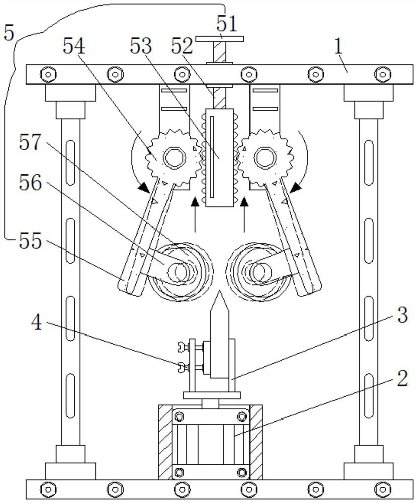
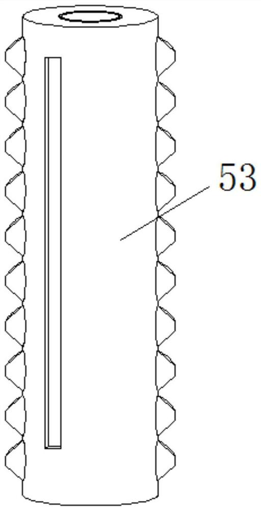
[0024] see Figure 1-2 , a tool grinding device for avoiding the impact of uneven knife edge on cutting accuracy, including a grinding assembly 5, the inside of the grinding assembly 5 is provided with a rotary rod 51, the bottom of the rotary rod 51 is welded with a first screw rod 52, and the bottom of the first screw rod 52 is The outer wall is threadedly connected with a rack 53, the left and right sides of the rack 53 are provided with teeth, and the structures on the left and right sides are the same and symmetrical. thread, the left side of the rack 53 is meshed with a gear 54, the bottom of the gear 54 is welded with a swing arm 55, the right side of the bottom of the swing arm 55 is welded with a fixing groove 56, and the inside of the fixing groove 56 is movably connected with a grinding roller 57, which is polished The back of the roller 57 is fixedly connected to the front of the second tapered shaft 9, and the grinding roller 57 is directly above the fixed plate 3...
Embodiment 2
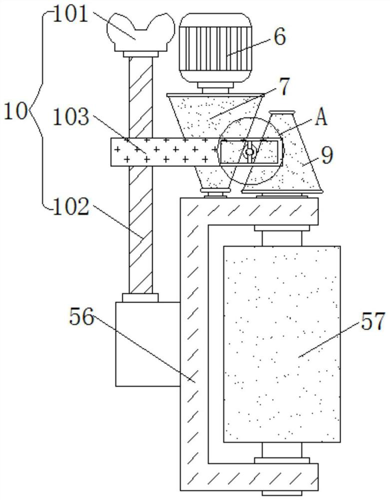
[0028] see Figure 3-5 , a tool grinding device for avoiding the impact of uneven knife edge on cutting accuracy, including an adjustment assembly 10, the inside of the adjustment assembly 10 is provided with a butterfly knob 101, the bottom of the butterfly knob 101 is welded with a second screw 102, the second screw 102 The outer wall of the movable frame 103 is threadedly connected with the movable frame 103, and the structures on the front and rear sides of the movable frame 103 are symmetrical and identical, and the inside of the movable frame 103 left side has threads suitable for the outer wall of the second screw mandrel 102, and the inside of the movable frame 103 right side A chute 104 is opened, and the inside of the chute 104 is slidably connected with a sliding plate 105 , and the back of the sliding plate 105 is riveted with a movable rod 106 , and the movable rod 106 is inserted into the inside of the transmission column 8 .
[0029] Also includes a support fram...
Embodiment 3
[0032] see Figure 1-5 , a tool grinding device for avoiding the impact of uneven knife edge on cutting accuracy, including a grinding assembly 5, the inside of the grinding assembly 5 is provided with a rotary rod 51, the bottom of the rotary rod 51 is welded with a first screw rod 52, and the bottom of the first screw rod 52 is The outer wall is threadedly connected with a rack 53, the left and right sides of the rack 53 are provided with teeth, and the structures on the left and right sides are the same and symmetrical. thread, the left side of the rack 53 is meshed with a gear 54, the bottom of the gear 54 is welded with a swing arm 55, the right side of the bottom of the swing arm 55 is welded with a fixing groove 56, and the inside of the fixing groove 56 is movably connected with a grinding roller 57, which is polished The back of the roller 57 is fixedly connected to the front of the second tapered shaft 9, and the grinding roller 57 is directly above the fixed plate 3...
PUM
 Abstract
Description
Claims
Application Information
 - R&D
- Intellectual Property
- Life Sciences
- Materials
- Tech Scout
- Unparalleled Data Quality
- Higher Quality Content
- 60% Fewer Hallucinations
Browse by: Latest US Patents, China's latest patents, Technical Efficacy Thesaurus, Application Domain, Technology Topic, Popular Technical Reports.
© 2025 PatSnap. All rights reserved.Legal|Privacy policy|Modern Slavery Act Transparency Statement|Sitemap|About US| Contact US: help@patsnap.com


