Eureka AIR delivers breakthrough ideas for toughest innovation challenges, trusted by R&D personnel around the world.

Telescopic shutter and using method thereof

A louver, U-shaped technology, applied in the field of retractable louvers, can solve problems such as prone to noise, affecting the normal use of windows, and the end of the shading plate is easy to break or deform, and achieve the effect of avoiding breakage or deformation

Inactive Publication Date: 2021-11-02
CHANGZHOU TAIERGE HEAVY IND MASCH CO LTD
View PDF3 Cites 2 Cited by
  • Summary
  • Abstract
  • Description
  • Claims
  • Application Information

AI Technical Summary

Problems solved by technology

[0003] The shades of existing blinds can only be rotated along a specific axis, and cannot be stored upwards, which affects the normal use of the window; the drawstring type blinds need to drill holes in the shades for the rope to pass through. The lifting and angle adjustment of the shading plate, however, reduces the shading performance of the louver after drilling. The existing drawstring louver is prone to noise when it is blown by the wind, especially in the office, which affects the mood of employees. Due to the end of the shading plate The end of the shading plate is not supported, and the end of the shading plate is easily broken or deformed when the external force hits the place, which affects the shading effect

Method used


Image

  • Telescopic shutter and using method thereof
  • Telescopic shutter and using method thereof
  • Telescopic shutter and using method thereof

Examples


Embodiment Construction

[0030] The present invention will be further described below with reference to the accompanying drawings and embodiments.

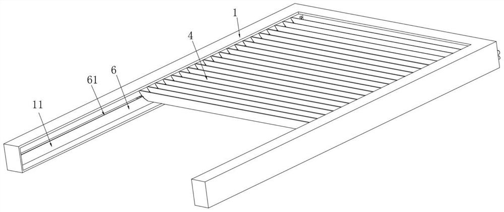
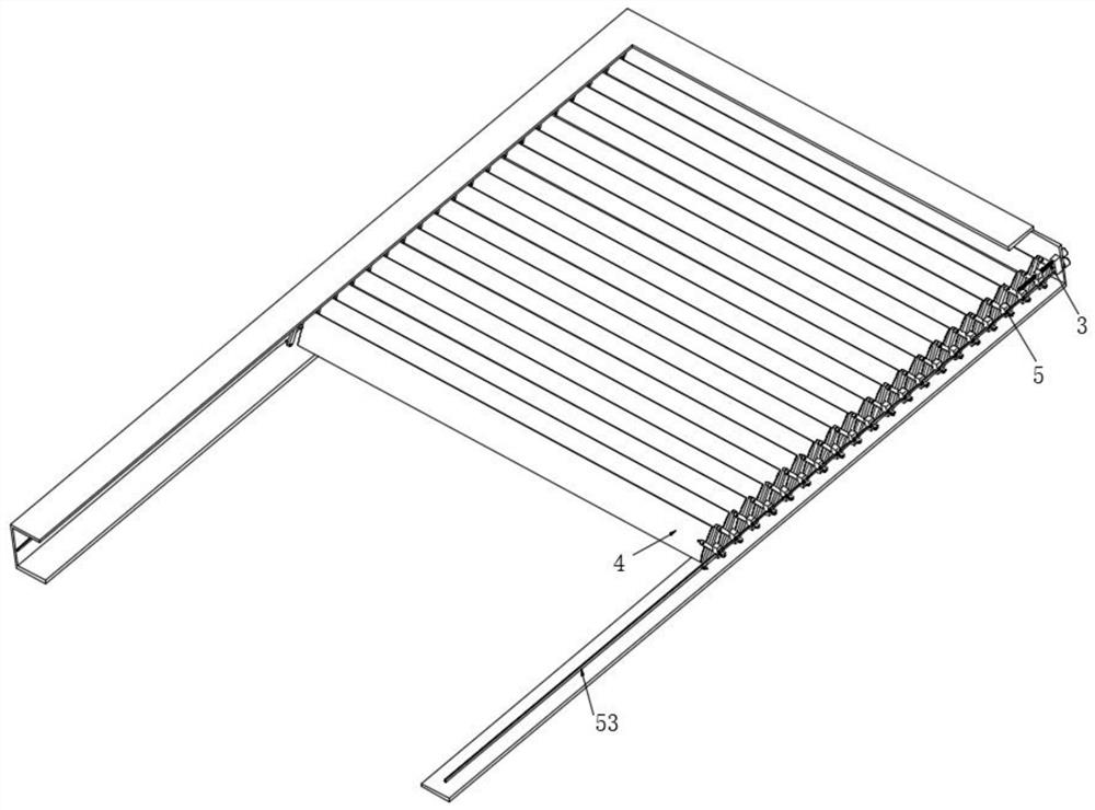
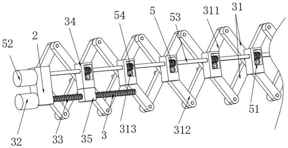
[0031] In the specific implementation process, if Figure 1-3 As shown, a telescopic shutters include:

[0032] The setting of the U-frame 1 and the U-shaped frame 1 supports other components, and the inner walls of the U-shaped frame 1 are provided with a housing groove 11 for accommodating other components;

[0033] Secure block 2, the fixing block 2 is fixed to the top end of the accommodating groove 11;

[0034] Lifting device 3, the lifting device 3 is disposed within the housing groove 11, the lifting device 3 including a plurality of shears 31, the shears 31, by the first link 311, the second link 312, and The rotating shaft 313 is composed, the central portion of the first link 311 and the second link 312 is hinged by the rotating shaft 313, and the rotating shaft 313 located at the top end is rotated to the fixed block 2, and the first link 311 at the...


PUM


Abstract

The invention provides a telescopic shutter and a using method thereof. The invention provides a telescopic blind window which comprises a U-shaped frame, a window frame, a window frame and a window frame, and the inner walls of the two sides of the U-shaped frame are each provided with a containing groove; the fixed block is fixed at the top end of the accommodating groove; the lifting device is arranged in the containing groove, and the lifting device comprises a plurality of shear fork rod sets; the invention further provides a using method of the telescopic shutter, and the using method comprises the steps that firstly, the output shaft of the lifting motor rotates to drive the lead screw to rotate, the threaded sleeve drives the uppermost sliding block to slide along the driving shaft and the containing groove, and through the arrangement of the shear fork rod set, the rotating shafts are adjusted at equal intervals; further, through forward and reverse rotation of the output shaft of the lifting motor, the distance of the rotating shaft is equidistantly increased and reduced, and stretching of the shutter is achieved; according to the telescopic shutter and the using method thereof, noise caused by shaking of the light shielding plate during wind blowing is avoided, and the condition that the light shielding plate is broken or deformed is avoided.

Description

Technical field [0001] The present invention relates to the field of blinds, and more particularly to a scalable shut-free window and a method of use thereof. Background technique [0002] Bloves are a model of the window, originated from China. In ancient Chinese architecture, there is a straight window, which is useful from the Danchao to the Han Dynasty. The vertical strip is called a straight window, and there is a horizontal straight, called a sleeper window. An original style of the lying on the blind, or it can be said that it is the original state of the blind. [0003] The visible plates with existing blinds can only be rotated along a particular axis, and cannot be accommodated, affecting the normal use of the window; the rope shutters need to be drilled on the shade, so that the rope word can be achieved The lifting and angle adjustment of the visor, however the drill is lowered, and the existing drawn rope shutters are prone to noise when they are blown, especially in...

Claims


Application Information

Patent Timeline
Patent Type & Authority Applications(China)
IPC IPC(8): E06B9/30E06B9/32E06B9/322
CPCE06B9/30E06B9/32E06B9/322
Inventor 李杰
Owner CHANGZHOU TAIERGE HEAVY IND MASCH CO LTD
Why Eureka
Eureka Blog
Learn More