
Auxiliary equipment for detecting compactness of transformer iron core

A transformer core and auxiliary equipment technology, applied in the field of transformers, can solve the problems of small transformer core deformation, difficult to observe, and low efficiency of manual detection, and achieve the effect of reducing errors

Active Publication Date: 2021-11-02
南通皓为电力科技有限公司
View PDF4 Cites 0 Cited by
  • Summary
  • Abstract
  • Description
  • Claims
  • Application Information

AI Technical Summary

Problems solved by technology

[0005] Aiming at the deficiencies of the prior art, the present invention provides an auxiliary device for detecting the tightness of the transformer iron core, which solves the problems that the deformation of the transformer iron core is small, it is difficult to observe with the naked eye, and the efficiency of manual detection is low

Method used


Image

  • Auxiliary equipment for detecting compactness of transformer iron core
  • Auxiliary equipment for detecting compactness of transformer iron core
  • Auxiliary equipment for detecting compactness of transformer iron core

Examples


Embodiment Construction

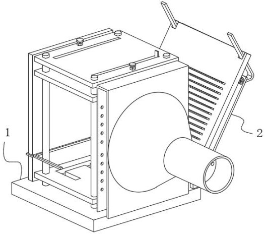
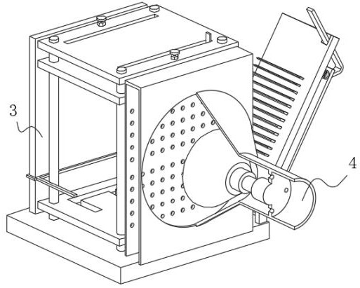
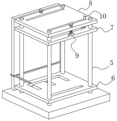
[0034] use Figure 1-Figure 8 An auxiliary device for detecting the tightness of a transformer core according to an embodiment of the present invention is described as follows.

[0035] Such as Figure 1-Figure 8 As shown, an auxiliary device for detecting the tightness of a transformer core according to the present invention includes a base 1; the outer surface on the right side of the base 1 is rotatably connected with a detection mechanism 2, and the left side of the detection mechanism 2 is provided with a display mechanism 3, The lower surface of the display mechanism 3 is fixedly connected to the upper surface of the base 1, the front of the display mechanism 3 is provided with a spraying mechanism 4, and the lower surface of the spraying mechanism 4 is fixedly connected to the upper surface of the base 1;

[0036] The detection mechanism 2 includes a splint 11, the inner surface of the splint 11 is slidably connected with an insert 12, the lower surface of the insert 12 ...


PUM


Abstract

The invention belongs to the field of transformers, and particularly relates to an auxiliary equipment for detecting the compactness of a transformer iron core, which comprises a base, the outer surface of the right side of the base is rotationally connected with a detection mechanism, and a display mechanism is arranged on the left side of the detection mechanism. According to the auxiliary equipment for detecting the compactness of the transformer iron core, by arranging the bottom plate and the top plate, when the equipment is used, the iron core of the transformer is placed in a gap between the top plate and the bottom plate, and the iron core of the transformer is mostly an EI iron core and can be exactly clamped in the EI-shaped clamping grooves in the bottom plate and the top plate, so that in the process of gradually stacking the iron core upwards, the base plate moves along with the iron cores, it is guaranteed that the iron cores cannot incline or deviate in the vertical direction, a set of iron cores are perpendicular to the upper surface of the base all the time, errors during detection are reduced, and the problems that when traditional clamping equipment fixes the iron cores, loose iron cores are prone to skew and deviate, and measurement errors are increased are solved.

Description

technical field [0001] The invention belongs to the field of transformers, in particular to an auxiliary device for detecting the tightness of transformer iron cores. Background technique [0002] The iron core is the main magnetic circuit part of the transformer. It is usually made of stacked hot-rolled or cold-rolled silicon steel sheets with high silicon content and coated with insulating paint. The iron core and the coil wound on it form a complete electromagnetic induction system. The transmission power of the power transformer depends on the material and cross-sectional area of ​​the iron core. [0003] In order to increase the power transmission efficiency and cross-sectional area, the iron cores are usually stacked in sheets. Since the sheet iron cores lack external fixing parts, after long-term use, the material will be deformed by heat, and the tightness between the iron cores will decrease, resulting in gaps. The gaps are small, and it is generally difficult to...

Claims


Application Information

Patent Timeline
IPC IPC(8): G01M13/00G01V11/00
CPCG01M13/00G01V11/00Y02T10/62
Inventor 金韬宋姗菲汤文健
Owner 南通皓为电力科技有限公司
Learn More