Self-cleaning surface cleaning machine

A cleaning machine and self-cleaning technology, used in cleaning machinery, cleaning equipment, manual floor scrubbing machinery, etc., can solve the problem of not solving the problem of water overflow, not considering the cleaning of sewage suction ports, etc.

Pending Publication Date: 2021-11-05
SHARKNINJA CHINA TECH CO LTD
View PDF5 Cites 4 Cited by
  • Summary
  • Abstract
  • Description
  • Claims
  • Application Information

AI Technical Summary

Problems solved by technology

This solution solves the drying problem of the roller brush after cleaning, but still does not solve the overflow problem when there is too much water, or the safety problem after the water overflows. At the same time, this patent does not consider the cleaning problem of the sewage suction port

Method used


Image

  • Self-cleaning surface cleaning machine
  • Self-cleaning surface cleaning machine
  • Self-cleaning surface cleaning machine

Examples


Embodiment 1

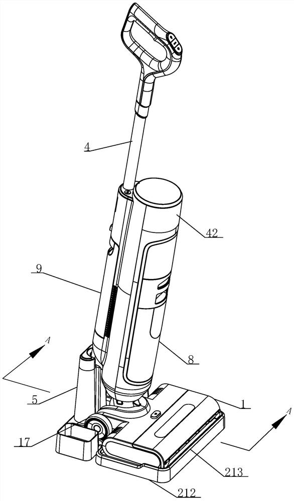
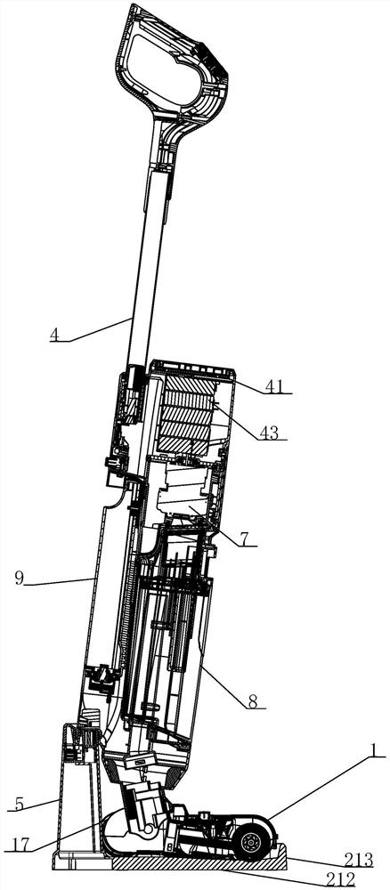
[0036] A kind of self-cleaning surface cleaning machine of the present invention, as Figure 1 to Figure 4 As shown, a surface cleaning machine with good self-cleaning effect includes a body 1, a cleaning dock 2, a cleaning roller 3 located at the bottom of the body 1, a handle bar 4 rotatably connected to the body, and a suction assembly. The dirt assembly includes a dirt suction fan 7 arranged on the handle bar 4, a dirt bucket 8, a dirt suction port 11 located in the body 1 facing the cleaning roller 3, and a delivery pipe 15 connecting the dirt suction port 11 and the dirt bucket 8 , the handle bar 4 is also provided with a water tank 9, in the present embodiment, the water tank 9 is located at the rear side of the dirt bucket 8, and an electric control unit 41 (not shown) is also arranged above the dirt bucket 8, The control part 41 and the battery pack 43, the control part 41 and the battery pack 43 are fixed on the handlebar 4, and are covered by the decorative part 42 ...

Embodiment 2

[0046] The difference between this embodiment and Embodiment 1 is the location and structure of the closed ribs.

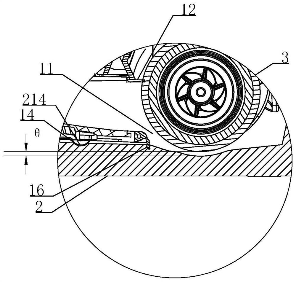
[0047] As another self-cleaning surface cleaner of the present invention, such as Figure 5 and Figure 6 As shown, the closed partition rib 6 is arranged in the receiving area 21, the closed partition rib 6 is arranged on the edge of the cleaning tank 211, and is adjacent to the flexible ground brush 16, and the closed partition rib 6 is connected to the lower surface of the body 1 conflict, the closed rib 6 extends to the coaming plate 213, and the closed rib 6 forms a liquid collection area with the base 212 and the coaming plate 213 on the side of the cleaning tank. When the surface cleaning machine is placed in the receiving area 21 Inside, the flexible floor brush 16 and the sewage suction port 11 are correspondingly located in the liquid collection area, so that the base 212 and the surrounding plate 213 on the side where the closed rib 6 and the cleaning ...


PUM


Abstract

The invention provides a self-cleaning surface cleaning machine which comprises a machine body, a cleaning dock, a cleaning roller arranged on the lower portion of the machine body, a handle rod rotationally connected to the machine body and a dirt suction assembly. The dirt suction assembly comprises a dirt suction fan arranged on the handle rod, a dirt containing barrel, a dirt suction opening formed in the machine body and facing the cleaning roller and a conveying pipeline connected with the dirt suction opening and the dirt containing barrel, and the cleaning dock comprises a bearing area for containing the machine body and a cleaning tank located on the front side of the bearing area and used for cleaning the cleaning roller. A closed partition rib is arranged between the machine body and the cleaning dock, the cleaning roller is located in the cleaning tank for rotary cleaning, the closed partition rib, the machine body and the cleaning dock form a liquid collection area, the dirt suction fan performs suction to form negative pressure, liquid in the cleaning tank is conveyed to the dirt containing barrel through the dirt suction opening and the conveying pipeline, and the closed partition rib, the machine body and the cleaning dock form a liquid collection area. Therefore, liquid is prevented from overflowing or splashing in the dirt suction process, and potential safety hazards caused by pollution to the ground or entering other positions of the cleaning dock are avoided.

Description

technical field [0001] The invention relates to the field of cleaning appliances, in particular to a surface cleaning machine. Background technique [0002] With the wide application of electrical equipment and the gradual improvement of the automation process, more and more electric cleaning devices are gradually accepted by people, such as sweeping robots, vacuum cleaners and floor washing machines. Now some surface cleaning devices are configured with a body and a cleaning roller arranged on the body, and the body drives the cleaning roller to rotate to mop the ground. However, the existing surface cleaning device requires the user to disassemble the cleaning roller after use and manually clean the cleaning roller, which results in poor user experience. With the advancement of technology, people have invented an automatic cleaning device for a surface cleaning machine, which usually includes a base, which includes a base and a connecting part arranged on one side of the ...

Claims


Application Information

Patent Timeline
IPC IPC(8): A47L11/282A47L11/30A47L11/40
CPCA47L11/282A47L11/302A47L11/40A47L11/4091
Inventor 朱泽春崔卫民朱广王海鑫
Owner SHARKNINJA CHINA TECH CO LTD
Why Eureka
Try Eureka