
Integrated thoracic cavity liquid pumping chair

A thoracic cavity and chair seat technology, which is applied in dental chairs, operating chairs, medical science, etc., can solve problems such as risks, discomfort for patients with chair backs, easy to change position, etc., and achieve the effect of convenient fluid extraction.

Pending Publication Date: 2021-11-05
中国人民解放军总医院第八医学中心
View PDF5 Cites 0 Cited by
  • Summary
  • Abstract
  • Description
  • Claims
  • Application Information

AI Technical Summary

Problems solved by technology

Due to the long time of thoracentesis, riding on the back of the chair with both legs is not only prone to fatigue, fatigue, easy to change positions, but also indecent posture, and at the same time, the positioning marks of the patient will be shifted during B-ultrasound positioning, which brings risks to the puncture , which increases the risk of operation; in addition, patients with narrow chair backs are uncomfortable, and fluid therapy and blood pressure cannot be monitored when necessary

Method used


Image

  • Integrated thoracic cavity liquid pumping chair
  • Integrated thoracic cavity liquid pumping chair
  • Integrated thoracic cavity liquid pumping chair

Examples


Embodiment 1

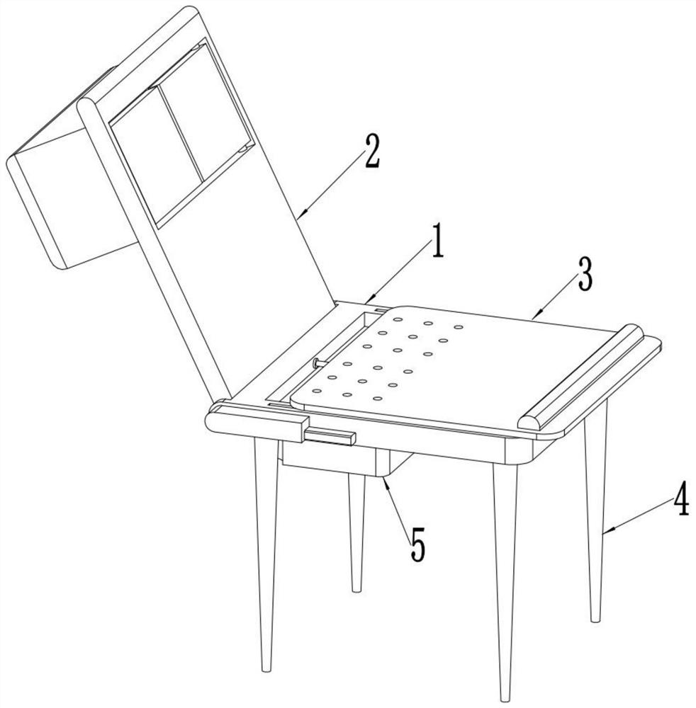
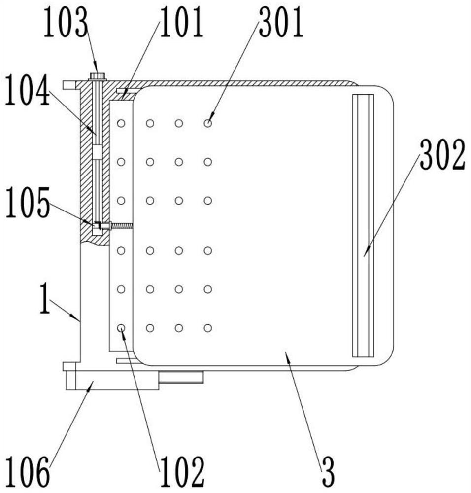
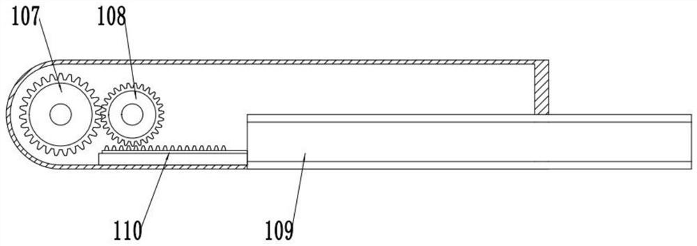
[0028] see Figure 1~3 , in the embodiment of the present invention, the integrated pleural cavity pumping chair includes a seat base 1 and a chair back 2 installed on one side of the seat base 1; a groove 101 is opened in the seat base 1, and the seat base 1 is used for sliding installation. For the backing plate 3 that the patient sits on, the groove 101 is equipped with a moving adjustment mechanism that drives the backing plate 3 to move back and forth on the seat 1, and the moving adjustment mechanism adjusts and adjusts the backing plate 3 to move on the seat 1, changing The position of the backing plate 3 is convenient for patients of different sizes to sit down. At the same time, the angle between the patient and the seat 1 can be adjusted to facilitate the extraction of the effusion inside the patient's pleural cavity; the chair back 2 rotates through the rotating shaft Installed on the seat 1, a regulator 106 for adjusting the rotation angle of the seat back 2 is ins...

Embodiment 2

[0035] see Figure 1~3 , in the embodiment of the present invention, the integrated pleural cavity pumping chair includes a seat base 1 and a chair back 2 installed on one side of the seat base 1; a groove 101 is opened in the seat base 1, and the seat base 1 is used for sliding installation. For the backing plate 3 that the patient sits on, the groove 101 is equipped with a moving adjustment mechanism that drives the backing plate 3 to move back and forth on the seat 1, and the moving adjustment mechanism adjusts and adjusts the backing plate 3 to move on the seat 1, changing The position of the backing plate 3 is convenient for patients of different sizes to sit down. At the same time, the angle between the patient and the seat 1 can be adjusted to facilitate the extraction of the effusion inside the patient's pleural cavity; the chair back 2 rotates through the rotating shaft Installed on the seat 1, a regulator 106 for adjusting the rotation angle of the seat back 2 is ins...


PUM


Abstract

The invention discloses an integrated thoracic cavity liquid pumping chair. The integrated thoracic cavity liquid pumping chair comprises a chair seat and a chair backrest installed on one side of the chair seat; a groove is formed in the chair seat, a cushion plate for a patient to sit down is installed on the chair seat in a sliding mode, and a movement adjusting mechanism for driving the cushion plate to move back and forth on the chair seat is installed in the groove; and the chair backrest is rotationally installed on the chair seat through a rotating shaft, and an adjuster for adjusting the rotating angle of the chair backrest is installed on the side edge of the chair seat. According to the integrated thoracic cavity liquid pumping chair, the cushion plate is adjusted to move on the chair seat through the movement adjusting mechanism, the position of the cushion plate is changed, and patients with different figures can conveniently sit down; meanwhile, the angle between the patient and the chair seat can be adjusted when the patient sits down, and hydrops in the thoracic cavity of the patient can be conveniently pumped out; and a cover plate is driven by a push-pull plate to be unfolded outwards, the head of the patient is placed on an ejector block, the arms of the patient are placed on the push-pull plate, the thoracic cavity of the patient is unfolded to the maximum position, and medical workers can conveniently pump liquid.

Description

technical field [0001] The invention relates to the technical field of medical devices, in particular to an integrated chest cavity pumping chair. Background technique [0002] Pleural effusion is a common and frequently-occurring disease in the Department of Respiratory Medicine. When the amount of pleural effusion is large or accompanied by pneumothorax, if there are clinical compression symptoms such as dyspnea, heart and mediastinal displacement, thoracentesis must be performed to relieve symptoms. , At the same time, keep the pleural fluid and send it to laboratory examination. When drawing fluid, the patient's ventral side faces the back of the chair, that is, he straddles an ordinary chair with a backrest, and puts his arms under the jaw on the narrow back of the chair. Due to the long time of thoracentesis, riding on the back of the chair with both legs is not only prone to fatigue, fatigue, easy to change positions, but also indecent posture, and at the same time, ...

Claims


Application Information

Patent Timeline
IPC IPC(8): A61G15/04A61G15/10A61G15/12A61M1/00
CPCA61G15/02A61G15/10A61G15/12A61G15/125
Inventor 安慧茹王天昊王子豪刘琳刘晓刘倩颖
Owner 中国人民解放军总医院第八医学中心
Learn More