Damp-proof shoe cabinet based on smart home

A smart home and shoe cabinet technology, applied to the legs of general furniture, the combination of two or more pieces of different types of furniture, furniture accessories, etc., can solve the problem of not being able to dry shoes, improve maintenance performance, and facilitate movement The effect of the stability performance with the fixed

Inactive Publication Date: 2020-11-03
胡立元
View PDF0 Cites 0 Cited by
  • Summary
  • Abstract
  • Description
  • Claims
  • Application Information

AI Technical Summary

Problems solved by technology

[0004] Based on the technical problem that the shoe cabinets used in the current smart home environment cannot dry shoes, this invention proposes a moisture-proof shoe cabinet based on smart home

Method used


Image

  • Damp-proof shoe cabinet based on smart home
  • Damp-proof shoe cabinet based on smart home
  • Damp-proof shoe cabinet based on smart home

Examples


Embodiment 1

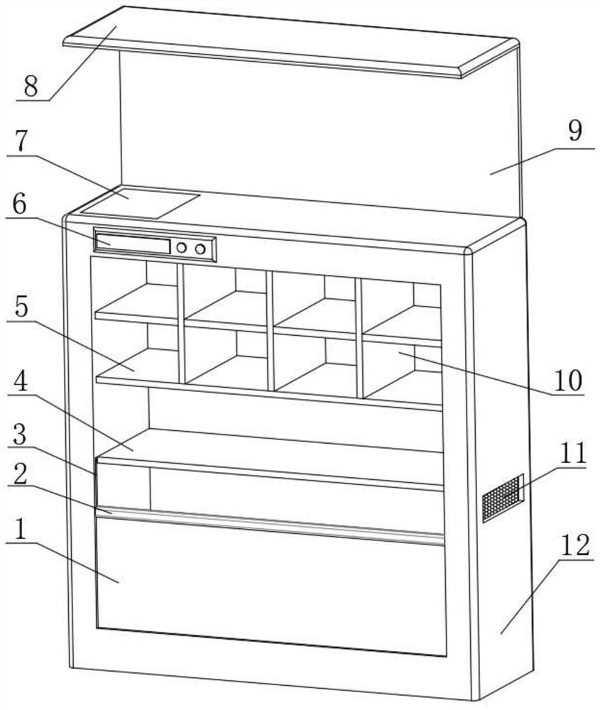
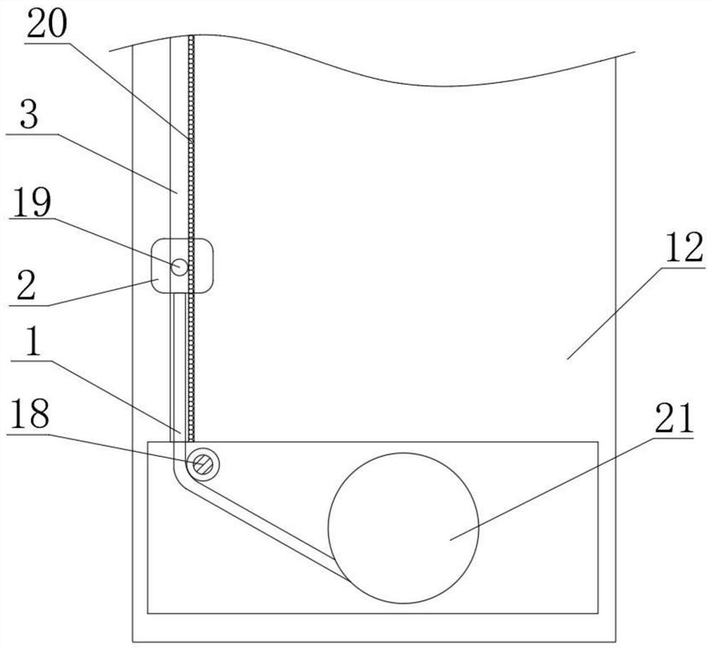
[0030] A moisture-proof shoe cabinet based on smart home, such as Figure 1-4 As shown, including the shoe cabinet chassis 12, a vertically arranged receiving groove is provided in the middle of one side of the shoe cabinet cabinet 12, and a horizontally arranged sealing middle plate 4 is fixed at the middle position between the inner walls of both ends of the shoe cabinet cabinet 12, The bottom positions of the inner walls at both ends of the shoe cabinet cabinet 12 are provided with vertically arranged sliding grooves 3, and between the two sliding grooves 3, a horizontally arranged running horizontal box 2 is slidingly clamped, and the bottom of the running horizontal box 2 passes through Bolts are fixed with a vertically arranged sealing roll 1, and the bottom position between the two ends of the shoe cabinet cabinet 12 is sleeved with a horizontally arranged cloth roll 21 through a bearing, and the circumferential outer wall of the cloth roll 21 is in contact with the seal...

Embodiment 2

[0034] A moisture-proof shoe cabinet based on smart home, such as Figure 1-5 As shown, the position on both sides of the bottom of the shoe cabinet cabinet 12 is provided with a vertically arranged moving groove 25, and the top inner wall of the moving groove 25 is provided with a fourth hole, and the circumferential inner wall of the fourth hole is sleeved with a vertically arranged groove. The hydraulic cylinder 26, the bottom position of the hydraulic cylinder 26 is fixed with the moving wheel 24, and the moving wheel 24 is socketed with the inside of the moving groove 25.

[0035] When the present embodiment is in use, in the second embodiment, a moving groove 25 is provided at the position of the shoe cabinet cabinet 12, and a vertical hydraulic cylinder 26 is fixed on the top of the moving groove 25, and the bottom position of the hydraulic cylinder 26 is fixed. Mobile wheels 24 are arranged, and in the process of moving the shoe cabinet, the lifting can be controlled b...


PUM


Abstract

The invention belongs to the technical field of smart home, particularly relates to a damp-proof shoe cabinet based on smart home, and provides the following scheme for solving the problem that an existing shoe cabinet for a smart home environment cannot dry shoes: the damp-proof shoe cabinet comprises a shoe cabinet box, and a vertically arranged storage groove is formed in the middle of one sideof the shoe cabinet box; a horizontally-arranged sealing middle plate is fixed to the middle position between the inner walls of the two ends of the shoe cabinet machine box. According to the invention, the transverse box is operated to ascend, the internal heating area is sealed through the sealing rolled cloth on one side, the heating effect is achieved in the heating area through the heating process of the heating net plate at the bottom, and the horizontal purification air outlet fan is installed at the top of one end of the transverse box; and the purification air outlet fan can circulate internal hot air to dry shoes placed inside, so that the maintenance performance of the whole device on the shoes is improved.

Description

technical field [0001] The invention relates to the technical field of smart home, in particular to a moisture-proof shoe cabinet based on smart home. Background technique [0002] Smart home is based on the residence as a platform, using integrated wiring technology, network communication technology, security technology, automatic control technology, audio and video technology to integrate the facilities related to home life, to build an efficient management system for residential facilities and family schedules, and to improve Home safety, convenience, comfort, artistry, and to achieve an environmentally friendly and energy-saving living environment. [0003] In the process of using the current smart home, because the current smart home is in use, and because the shoe cabinet in the current smart home environment is in use, the process of drying the wet shoes cannot be done in the rainy weather. Shoes are prone to easy, even moldy process. Contents of the invention [...

Claims


Application Information

Patent Timeline
Patent Type & Authority Applications(China)
IPC IPC(8): A47B61/04A47B91/06A47B97/00A47L23/20A47B83/00A47C4/04
CPCA47B61/04A47B83/00A47B91/06A47B97/00A47B2220/0091A47C4/04A47L23/205
Inventor 胡立元
Owner 胡立元
Why Eureka
Try Eureka