Connector separating mechanism

A separation mechanism and connector technology, applied in the direction of connection, conveyor, conveyor objects, etc., can solve the problems of wrong feeding, easy to fall, unstable clamping process, etc., and achieve accurate positioning and feeding accuracy. high effect

Active Publication Date: 2021-11-05
季华科技有限公司
View PDF11 Cites 0 Cited by
  • Summary
  • Abstract
  • Description
  • Claims
  • Application Information

AI Technical Summary

Problems solved by technology

[0004] However, at present, the loading of connectors is mostly done manually, and the efficiency and automation are kept at the lowest level, so it is difficult to achieve a major breakthrough. The automatic feeding of connectors, but the way of automatic feeding of the existing vibrating plate will cause multiple connectors to be in close contact with each other. Due to the structure of the connector itself, it is easy to place the relative If the adjacent connectors are clamped at the same time, not only the feeding error will occur, but also the clamping process will become unstable and prone to falling.

Method used


Image

  • Connector separating mechanism
  • Connector separating mechanism
  • Connector separating mechanism

Examples


Embodiment Construction

[0032] The following will clearly and completely describe the technical solutions in the embodiments of the present application with reference to the accompanying drawings in the embodiments of the present application. Obviously, the described embodiments are only some of the embodiments of the present application, not all of them. The components of the embodiments of the application generally described and illustrated in the figures herein may be arranged and designed in a variety of different configurations. Accordingly, the following detailed description of the embodiments of the application provided in the accompanying drawings is not intended to limit the scope of the claimed application, but merely represents selected embodiments of the application. Based on the embodiments of the present application, all other embodiments obtained by those skilled in the art without making creative efforts belong to the scope of protection of the present application.

[0033] It should ...


PUM


Abstract

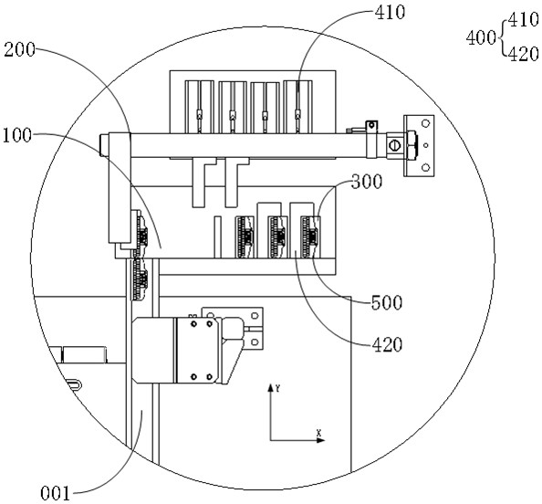
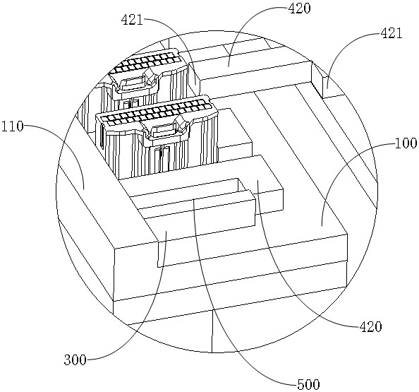
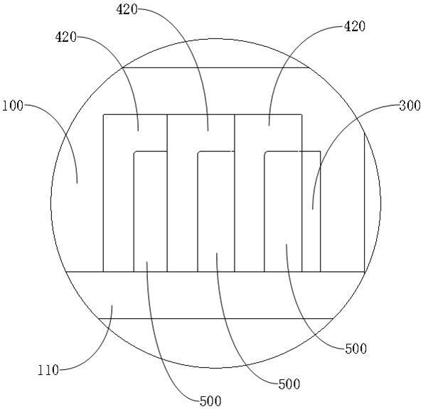
The invention provides a connector separating mechanism, and relates to the technical field of material conveying. According to the technical scheme provided by the invention, the connector separating mechanism is characterized by comprising a sliding table connected with a connector feeding channel, a material pushing component used for pushing connectors to move, a first limiting component and a second limiting component, wherein the first limiting component is arranged on the sliding table and used for limiting the connectors in the X-axis direction; the second limiting component comprises a power piece and a limiting piece arranged on the power piece; and the power piece drives the limiting piece to move, so that the limiting piece, the first limiting component and the sliding table form an independent limiting space, the connectors are limited in the X-axis direction and the Y-axis direction, and the connectors are separated from each other. The connector separating mechanism provided by the invention has the advantages that the connectors are separated and fed, the positioning is accurate, and the feeding precision is high.

Description

technical field [0001] The present application relates to the technical field of material conveying, in particular, to a connector separation mechanism. Background technique [0002] In the field of automation, feeding is a key part of achieving the goal. Unmanned, automated and intelligent feeding is the general trend and the most important thing. [0003] In the injection molding industry, the feeding of plastic parts needs to be a prerequisite for subsequent automation operations. Therefore, the automation of feeding plastic parts is particularly important. The stable and automatic feeding of automotive connectors is an important step in the environment where the automatic production rate of automobiles is extremely high. The realization of automatic feeding of connectors will lay a solid foundation for a series of subsequent automation operations. [0004] However, at present, the loading of connectors is mostly done manually, and the efficiency and automation are kept ...

Claims


Application Information

Patent Timeline
IPC IPC(8): B65G27/02B65G11/02B65G47/88H01R43/00
CPCB65G27/02B65G11/023B65G47/8815H01R43/00
Inventor 唐绍宾陶红保
Owner 季华科技有限公司
Why Eureka
Try Eureka