Ring-spinning frame spinning tension collecting device
A collection device and spinning frame technology, applied in the direction of textiles and papermaking, can solve the problems of fragile external structure, unfavorable use, and easy damage of precision devices, and achieve the effect of being convenient to use in complex environments and closely arranged
- Summary
- Abstract
- Description
- Claims
- Application Information
AI Technical Summary
Problems solved by technology
Method used
Image
Examples
Embodiment 1
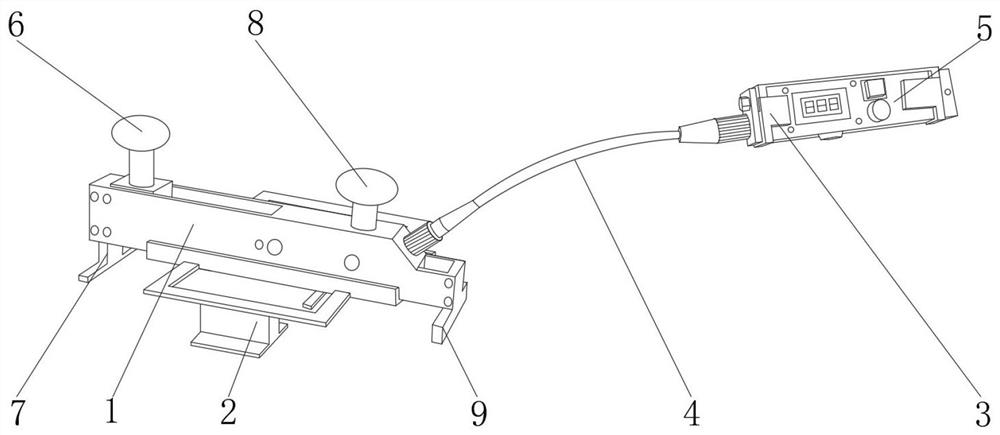
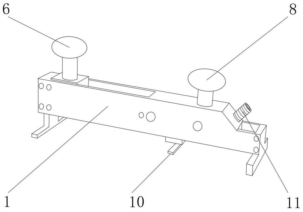
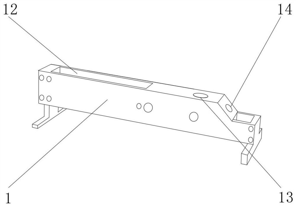
[0029] like Figure 1-5 As shown, the spinning tension collecting device of the ring spinning frame includes the front main body 1 of the collecting device and the control handle 5 of the collecting device. The No. 1 support leg 7 and the No. 2 support leg 9 are fixedly connected, and a sliding groove 12, a socket 13, and a wiring hole 14 are provided on the outer side of the front-end body 1 of the acquisition device, and a movable knob 6 is fixedly connected to the inner side of the sliding groove 12. The inner side of the hole 13 is fixedly connected with the fixing button 8 .
[0030]The outer side of the wiring hole 14 is fixedly connected with a No. 1 connector 11, the bottom end of the front body 1 of the collection device is fixedly connected with a measuring component 10, one end of the control handle 5 of the collection device is fixedly connected with a No. 2 connector 15, and the bottom of the collection device control handle 5 The outer side is fixedly connected ...
Embodiment 2
[0034] like Figure 1-4 As shown in , 6, the spinning tension collection device of the ring spinning frame includes the front main body 1 of the collection device and the control handle 5 of the collection device. The two ends are fixedly connected with a No. 1 support leg 7 and a No. 2 support leg 9, and the outer side of the front body 1 of the collection device is provided with a sliding groove 12, a socket 13, and a wiring hole 14, and the inner side of the sliding groove 12 is fixedly connected with a movable knob 6 , The inner side of the jack 13 is fixedly connected with the fixing button 8 .
[0035] The outer side of the wiring hole 14 is fixedly connected with a No. 1 connector 11, the bottom end of the front body 1 of the collection device is fixedly connected with a measuring component 10, one end of the control handle 5 of the collection device is fixedly connected with a No. 2 connector 15, and the bottom of the collection device control handle 5 The outer side ...
Embodiment 3
[0039] like Figure 1-4 , 7, the ring spinning frame spinning tension collection device includes the collection device front body 1 and the collection device control handle 5, the lower end of the collection device front body 1 is fixedly connected with a portable rack 2, the collection device front body 1 The two ends are fixedly connected with a No. 1 support leg 7 and a No. 2 support leg 9, and the outer side of the front body 1 of the collection device is provided with a sliding groove 12, a socket 13, and a wiring hole 14, and the inner side of the sliding groove 12 is fixedly connected with a movable knob 6 , The inner side of the jack 13 is fixedly connected with the fixing button 8 .
[0040] The outer side of the wiring hole 14 is fixedly connected with a No. 1 connector 11, the bottom end of the front body 1 of the collection device is fixedly connected with a measuring component 10, one end of the control handle 5 of the collection device is fixedly connected with a...
PUM
 Abstract
Description
Claims
Application Information
 - R&D
- Intellectual Property
- Life Sciences
- Materials
- Tech Scout
- Unparalleled Data Quality
- Higher Quality Content
- 60% Fewer Hallucinations
Browse by: Latest US Patents, China's latest patents, Technical Efficacy Thesaurus, Application Domain, Technology Topic, Popular Technical Reports.
© 2025 PatSnap. All rights reserved.Legal|Privacy policy|Modern Slavery Act Transparency Statement|Sitemap|About US| Contact US: help@patsnap.com


