Light guide structure for realizing high brightness by low-power LED

A light-guide structure and high-brightness technology, which is applied to semiconductor devices, light sources, and optical signals of light-emitting elements, can solve problems such as inability to make light guides and PCBA, design position deviation, and large size chain between LEDs and light guides, so as to improve optical utilization. High efficiency and good thermal conductivity

Pending Publication Date: 2021-11-05
北京海纳川海拉三河车灯有限公司
View PDF0 Cites 2 Cited by
  • Summary
  • Abstract
  • Description
  • Claims
  • Application Information

AI Technical Summary

Problems solved by technology

[0003] However, the disadvantages of the existing LED car lights are: 1. The light emitted by the LED is incident into the light guide at about 90 degrees, and the light at a certain angle with the LED cannot be incident into the light guide. 2. Most of the light guide and PCBA are not installed. On the same part, due to mold reasons, it is impossible to make a direct limit structure between the light guide and PCBA, resulting in a large size chain between the LED and the light guide after the actual installation, and there is a certain deviation in the design position of the LED and the light guide after the actual product is installed. To this end, we propose a low-power LED to achieve high-brightness light guide structure

Method used


Image

  • Light guide structure for realizing high brightness by low-power LED
  • Light guide structure for realizing high brightness by low-power LED
  • Light guide structure for realizing high brightness by low-power LED

Examples


Embodiment Construction

[0018] In order to make the technical means, creative features, goals and effects achieved by the present invention easy to understand, the present invention will be further described below in conjunction with specific embodiments.

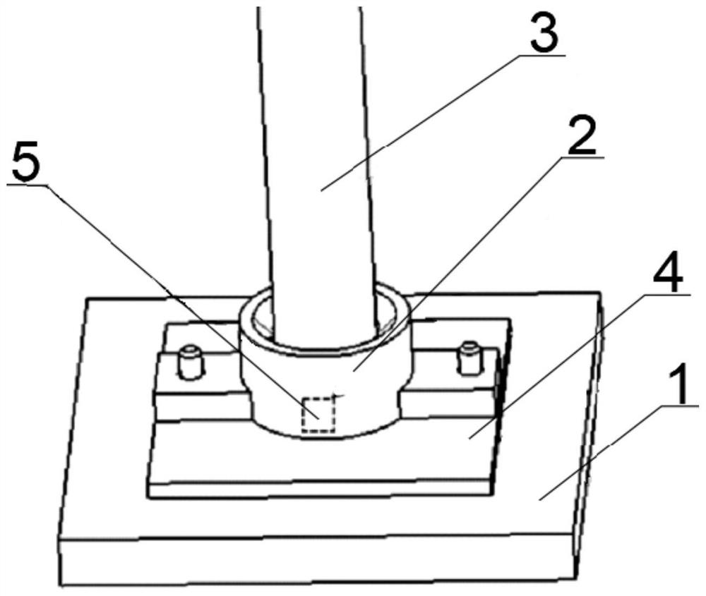
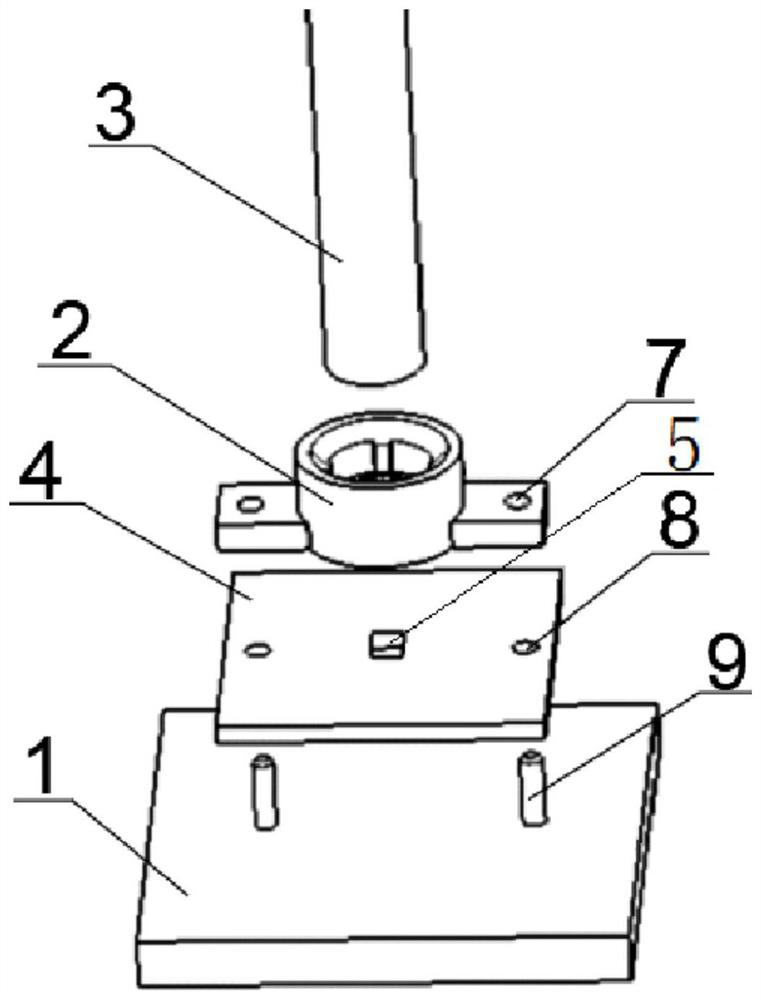
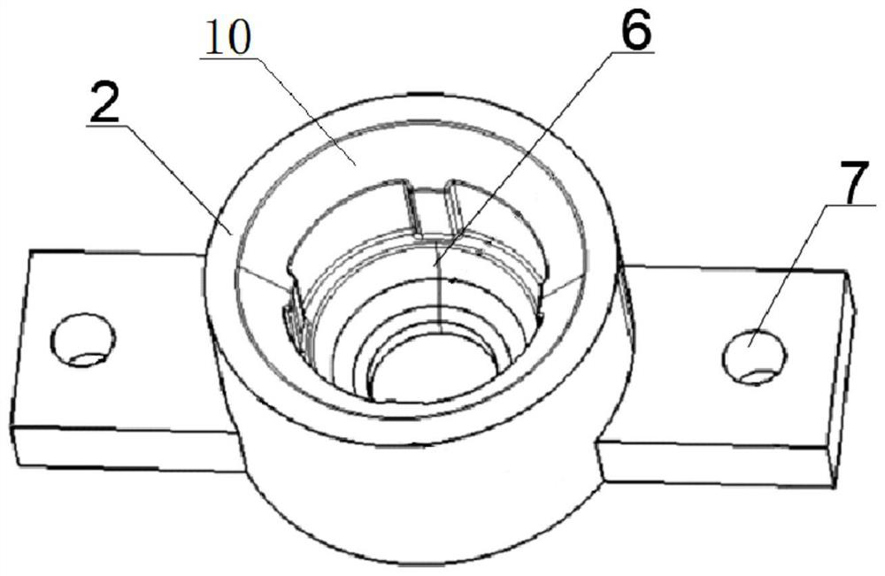
[0019] Such as Figure 1-3 As shown, a low-power LED realizes a high-brightness light guide structure, including a bracket 1 and a concentrator 2, a PCBA4 is arranged on the top of the bracket 1, an LED wick 5 is installed on the top of the PCBA4 through a mounting seat, and the outside of the top of the PCBA4 is arranged There is a light concentrator 2, an optical reflection mirror 6 is glued inside the light concentrator 2, and a light guide column 3 is set on the top of the light concentrator 2.

[0020] Wherein, internal thread fixing pipes 9 are welded at both ends of the top of the bracket 1 .

[0021] In this example, if figure 2 As shown, the internal threaded fixing tube 9 facilitates the installation of the concentrator 2 and the PCBA...


PUM


Abstract

The invention discloses a light guide structure for realizing high brightness by a low-power LED. The light guide structure comprises a support and a light condenser, a PCBA is arranged on the top of the support, an LED lamp wick is installed on the top of the PCBA through an installation base, the light condenser is arranged on the outer side of the top of the PCBA, an optical reflection mirror face is glued in the light condenser, and a light guide column is arranged on the top of the light condenser in a sleeved mode. Compared with a conventional LED lighting light guide mode, the condenser is additionally arranged, the condenser can play a role in collecting light which cannot be directly emitted into the light guide and reflecting the light into the light guide again, meanwhile, the condenser can also reduce the effect that deviation exists between the position relation of a traditional light guide and an LED and actual assembly matching, and therefore the LED optical utilization rate is increased. The objective of low-power high brightness is achieved and the light guide structure is suitable for being widely popularized and used.

Description

technical field [0001] The invention relates to the technical field of auto parts, in particular to a light guide structure for realizing high brightness with low-power LEDs. Background technique [0002] Car headlights, also known as car headlights and car LED daytime running lights, as the eyes of a car, are not only related to the external image of a car owner, but also closely related to driving at night or in bad weather conditions. Currently, there are In the matching structure of light guides and LEDs used in car lights. [0003] However, the disadvantages of the existing LED car lights are: 1. The light emitted by the LED is incident into the light guide at about 90 degrees, and the light at a certain angle with the LED cannot be incident into the light guide. 2. Most of the light guide and PCBA are not installed. On the same part, due to mold reasons, it is impossible to make a direct limit structure between the light guide and PCBA, resulting in a large size chain...

Claims


Application Information

Patent Timeline
Patent Type & Authority Applications(China)
IPC IPC(8): F21S41/37F21S41/39F21S41/24F21S41/29F21S43/237F21S43/27F21S43/33F21S43/37F21S45/48F21V23/00F21W102/00F21W103/55F21W107/10F21Y115/10
CPCF21S41/37F21S41/39F21S41/24F21S41/29F21S43/33F21S43/37F21S43/237F21S43/27F21S45/48F21V23/005F21W2102/00F21W2103/55F21W2107/10F21Y2115/10
Inventor 江浦李萌余鹏何明
Owner 北京海纳川海拉三河车灯有限公司
Why Eureka
Try Eureka