Heat exchange device

A technology of heat exchange device and heat exchange tube, applied in the direction of heat exchanger type, indirect heat exchanger, heat transfer modification, etc. The effect of prolonging the service life and maintenance interval

Pending Publication Date: 2021-11-05
北京中电联节能技术有限公司
View PDF3 Cites 0 Cited by
  • Summary
  • Abstract
  • Description
  • Claims
  • Application Information

AI Technical Summary

Problems solved by technology

[0004] Aiming at the above-mentioned deficiencies of the prior art, the technical problem to be solved by the present invention is to provide a heat exchange device, which avoids the traditiona

Method used


Image

  • Heat exchange device
  • Heat exchange device
  • Heat exchange device

Examples


Embodiment Construction

[0028] The specific implementation manners of the present invention will be further described in detail below in conjunction with the accompanying drawings.

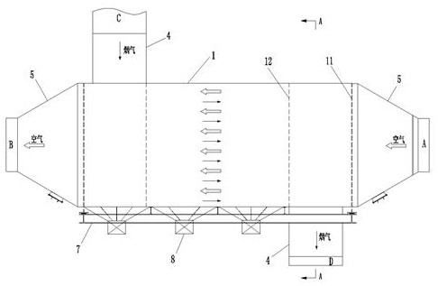
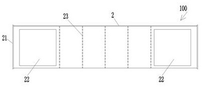
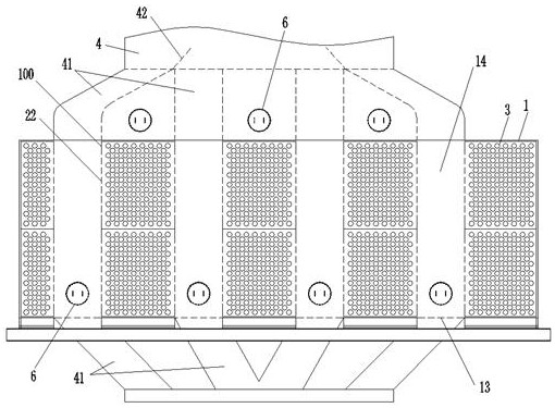
[0029] See figure 1 , figure 2 , a specific embodiment of a heat exchange device, including a cylindrical main casing 1, the two ends of the main casing 1 are respectively sealed with sealing plates 11 so as to form a heat exchange space in the main casing 1, the main casing 1 There are a plurality of heat exchange tubes 3 inside, the heat exchange tubes 3 correspond to the length direction of the main shell 1 and the two ends respectively pass through the corresponding sealing plate 11, and the side wall of the main shell 1 is connected with two first media The two ends of the pipeline 4 and the main shell 1 are respectively connected with the second medium pipeline 5, and the second medium pipeline 5 communicates with each heat exchange tube 3; a plurality of heat exchange module units 100 are detachably installed in...


PUM


Abstract

The invention relates to a heat exchange device which comprises a cylindrical main shell, two ends of the main shell are connected with sealing plates and a second medium pipeline, a sidewall of the main shell communicates with two first medium pipelines, a plurality of heat exchange module units are arranged in the main shell, each heat exchange module unit comprises a cylindrical sub-shell, two ends of each sub-shell penetrate through the sealing plates at the corresponding ends and are respectively connected with end plates, a plurality of heat exchange pipes are mounted in the sub-shell, two ends of each heat exchange pipe penetrate through the end plates at the corresponding ends and communicate with the second medium pipelines at the corresponding ends, partition plates adjacent to the two sealing plates are further arranged in the main shell in a one-to-one mode, the sub-shell penetrates through the partition plates, first medium circulation openings are respectively formed in the portions, located between the sealing plates and the partition plates at the corresponding ends, of two ends of the sidewall of the sub-shell, and the two first medium pipelines are respectively located at two ends of the sidewall of the main shell and communicate with the first medium circulation openings in the corresponding ends. According to the device, the independent heat exchange module units are adopted, manufacturing and installation are facilitated, the field construction amount can be reduced, and the heat exchange efficiency can be effectively guaranteed.

Description

technical field [0001] The invention belongs to the technical field of air preheaters in machinery, and in particular relates to a heat exchange device. Background technique [0002] In large-scale heating equipment such as boilers, the flue gas discharged from the flue gas pipe carries a large amount of heat. By adding a heat exchange device and using the heat exchange tube of the heat exchange device, the heat of the flue gas can be transferred to the circulating air for heat transfer. Recycling can also reduce the energy consumption of equipment, which is involved in the prior art such as CN110849180A, CN111692899A, CN 110939929A, etc. [0003] At present, for large-scale boiler equipment, the corresponding heat exchange devices mostly use rotary air preheaters, and some also use tubular air preheaters. Among them, the problems of the rotary air preheater are: 1. During the operation of the equipment, the rotor blades wear quickly, and the air leakage of the equipment gr...

Claims


Application Information

Patent Timeline
IPC IPC(8): F23L15/00F28D7/16F28F13/12
CPCF23L15/00F28D7/16F28F13/12Y02E20/34
Inventor 廖兴中欧胡林
Owner 北京中电联节能技术有限公司
Why Eureka
Try Eureka