Intelligent robot for machine room inspection

A kind of intelligent robot and robot technology, applied in the field of intelligent robot, can solve the problems affecting the safety of the information computer room, low efficiency, insufficient patrol inspection, etc., and achieve the effect of simple inspection work, improved work efficiency, and convenient inspection

Pending Publication Date: 2021-11-05
童旭亮
View PDF10 Cites 3 Cited by
  • Summary
  • Abstract
  • Description
  • Claims
  • Application Information

AI Technical Summary

Problems solved by technology

[0002] At present, inspections of equipment in information computer rooms are mainly carried out manually; under the impression of factors such as personnel trial status, psychological quality, work experience, and technical level, there are often problems such as heavy workload, low efficiency, and insufficient inspections.
[0003] At present, the power environment monitoring of the computer room generally adopts the configuration system solution. Compared with the embedded system, its structure is complex and the intermediate links are scattered. In case of network disconnection or crash, the monitoring system will be useless
[0004] Due to the limitation of manual inspection, the lack of unified and centralized management of multiple devices, the inability to accurately grasp the conditions of each device and the environment in the computer room, resulting in equipment failures that cannot be detected and processed in time, seriously affecting the security of the information computer room

Method used


Image

  • Intelligent robot for machine room inspection
  • Intelligent robot for machine room inspection
  • Intelligent robot for machine room inspection

Examples


Embodiment 1

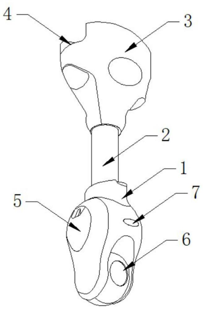
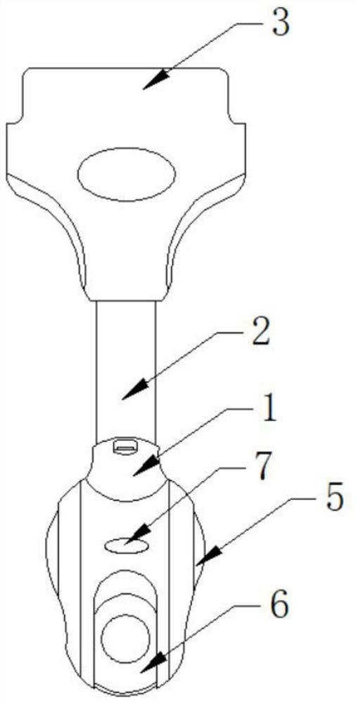
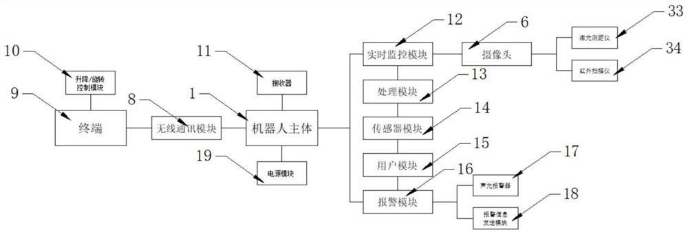
[0027] Such as Figure 1-6 As shown, the present invention provides an intelligent robot for machine room inspection, including a robot main body 1, a camera 6, a wireless communication module 8 and a terminal 9. The upper end of the robot main body 1 is provided with a rotating lifting rod 2, and the rotating lifting rod 2 One end is provided with a moving block 3, the upper end of the moving block 3 is provided with a chute 4, both sides of the robot main body 1 are provided with a battery cover 5, the bottom of the robot main body 1 is provided with a camera 6, and a supplementary light is provided directly above the camera 6 Light 7, the robot main body 1 is connected with the terminal 9 through the wireless communication module 8, the terminal 9 is provided with a lift / rotation control module 10, the robot main body 1 includes a receiver 11, a real-time monitoring module 12, a processing module 13, a sensor module 14, a user module 15 and alarm module 16.

[0028] Furthe...


PUM


Abstract

The invention discloses an intelligent robot for machine room inspection, which comprises a robot main body, a camera, a wireless communication module and a terminal, and is characterized in that the robot main body comprises a receiver, a real-time monitoring module, a processing module, a sensor module, a user module and an alarm module. According to the invention, real-time transmission of inspection monitoring images is carried out through the real-time monitoring module, detection is carried out through the sensor module, each camera is provided with a corresponding RFID tag, and data of a plurality of cameras with different RFID tags are transmitted through the RFID inductor, so that the data detected by each camera can be integrated and inspection is facilitated. The user can check different contents and operations according to different permissions, and the number of the robot main bodies which can be controlled by each user is also set, so that the management of the robot main bodies is more convenient, a large amount of manual inspection is not needed, the safety of workers can be guaranteed, and the overall working efficiency is improved.

Description

technical field [0001] The invention relates to the technical field of computer room inspection, in particular to an intelligent robot for computer room inspection. Background technique [0002] At present, inspections of equipment in information computer rooms are mainly carried out manually; due to factors such as personnel trial status, psychological quality, work experience, and technical level, there are often problems such as heavy workload, low efficiency, and insufficient inspections. [0003] At present, the power environment monitoring of the computer room generally adopts the configuration system solution. Compared with the embedded system, its structure is complex and the intermediate links are scattered. In case of network disconnection or crash, the monitoring system will be useless. [0004] Due to the limitations of manual inspections and the lack of centralized management of multiple devices, it is impossible to accurately grasp the conditions of each devic...

Claims


Application Information

Patent Timeline
Patent Type & Authority Applications(China)
IPC IPC(8): G07C1/20H04N5/225H04N5/232H04N7/18G06K17/00G08B7/06G08B25/08H04L29/06B25J5/02B25J11/00B25J19/02F16M11/04F16M11/06F16M11/18F16M13/02G01D21/02
CPCG07C1/20H04N7/181G06K17/0029G08B7/06G08B25/08H04L63/0428H04L63/105B25J5/02B25J11/00B25J19/023B25J19/02F16M13/02F16M11/046F16M11/06F16M11/18G01D21/02H04N23/56H04N23/695
Inventor 童旭亮金亮张云岑姚钦锋高福义王允非张春辉许寅冬
Owner 童旭亮
Why Eureka
Try Eureka