
Current blocking method and device for direct current transmission system fault and system

A technology of DC transmission system and transmission system, which is applied in the direction of circuit device, AC network circuit, AC network voltage adjustment, etc., and can solve the problems of poor fault ride-through ability of DC transmission system

Pending Publication Date: 2021-11-05
GUANGZHOU BUREAU CSG EHV POWER TRANSMISSION
View PDF2 Cites 2 Cited by
  • Summary
  • Abstract
  • Description
  • Claims
  • Application Information

AI Technical Summary

Problems solved by technology

[0005] However, in the existing DC fault ride-through method, after fault isolation, the converter station will be out of operation. Therefore, when this method is applied to the multi-terminal DC transmission When the fault current on the DC transmission line drops to zero, the converter station connected to the adjacent line must also be out of operation, that is, all converter stations in the DC transmission system will all be out of operation, resulting in the fault ride-through capability of the DC transmission system poor

Method used


Image

  • Current blocking method and device for direct current transmission system fault and system
  • Current blocking method and device for direct current transmission system fault and system
  • Current blocking method and device for direct current transmission system fault and system

Examples


Embodiment Construction

[0051] In order to make the purpose, technical solution and advantages of the present application clearer, the present application will be further described in detail below in conjunction with the accompanying drawings and embodiments. It should be understood that the specific embodiments described here are only used to explain the present application, and are not intended to limit the present application.

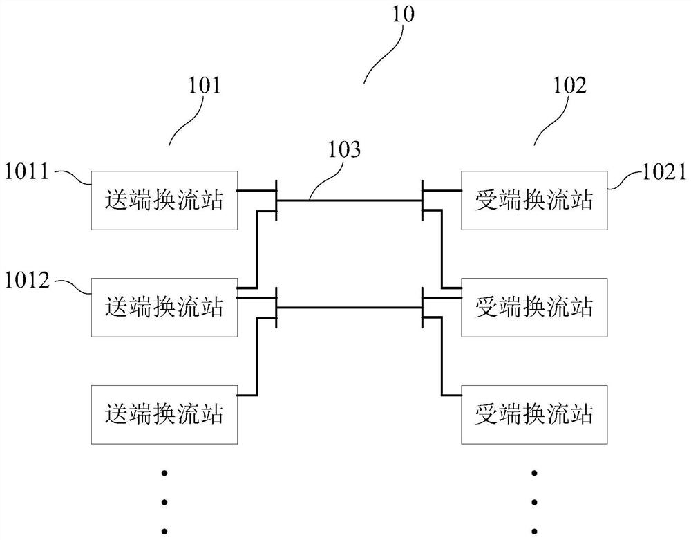
[0052] The current blocking method for DC transmission system fault provided by this application can be applied to such as figure 1 shown in the application environment. Wherein, the multi-terminal HVDC power transmission system 10 includes a plurality of sending-end converter stations 101 and a plurality of receiving-end converter stations 102, and the respective DC The output port is connected to the DC transmission line 103 where the first sending-end converter station 1011 is located, and connected to a receiving-end converter station 1021 through the DC transmission ...


PUM


Abstract

The invention relates to a current blocking method and device for a direct-current power transmission system fault, a multi-terminal direct-current power transmission system and a storage medium, the method is applied to the multi-terminal direct-current power transmission system, and the system comprises a plurality of sending-end converter stations and a plurality of receiving-end converter stations. Under the condition that a fault occurs in a direct-current power transmission line, a fault current on the direct-current power transmission line is obtained, and a target voltage of a first sending end converter station which enables the fault current of the direct-current power transmission line to be zero is determined according to the fault current and a preset reference current; and after the first sending-end converter station is controlled to output the target voltage, a switch between the direct-current transmission line and the first sending-end converter station is controlled to be switched off, and under the condition, the current of the second sending-end converter station flows into the first sending-end converter station. According to the method, the fault current can be reduced to zero under the condition that the second sending end converter station does not need to quit operation, so that fault current blocking is realized; and then, the second sending end converter station continues to operate, and the fault ride-through capability of the direct-current power transmission system is improved.

Description

technical field [0001] The present application relates to the technical field of direct current fault ride-through of direct current transmission, and in particular to a current blocking method and device, a multi-terminal direct current transmission system and a storage medium for a fault in a direct current transmission system. Background technique [0002] The DC transmission system based on modular multilevel converter based high voltage direct current (MMC-HVDC for short) technology has the advantages of flexible control, high power supply reliability, and can realize multi-power supply and multi-drop receiving points. It has good application prospects in the fields of large-scale renewable energy generation integration, multi-energy complementarity and friendly grid connection. [0003] Although the flexible HVDC technology has many advantages, it faces challenging problems such as DC fault ride-through. When a pole-to-ground short-circuit fault occurs on the HVDC tran...

Claims


Application Information

Patent Timeline
IPC IPC(8): H02J3/36H02J3/12
CPCH02J3/36H02J3/12H02J2003/365Y02E60/60
Inventor 朱博徐攀腾严海健谷裕李建勋宋述波郑星星李倩杨学广
Owner GUANGZHOU BUREAU CSG EHV POWER TRANSMISSION
Learn More