Down filling machine down filling pipe mechanism with down filling depth adjusting function

A down filling machine, deep technology, applied in sewing tools, toys, entertainment, etc., can solve the problems of bending or deformation of the sealing ring, easy wear of the sealing ring, weakening of the air pressure of the down filling tube, etc., to reduce wear and tear Chance, the effect of increasing performance

Active Publication Date: 2021-11-09
广东鸿图实业有限公司
View PDF19 Cites 2 Cited by
  • Summary
  • Abstract
  • Description
  • Claims
  • Application Information

AI Technical Summary

Problems solved by technology

[0002] When filling toys or clothing, a down filling machine is used. Generally, the object to be filled is placed on the down filling tube of the down filling machine, and the inside of the object is filled with down through the down filling tube. The convenience of using the down machine makes the down filling machine suitable for down filling processing of different depths. The existing down filling tube is generally composed of an outer tube and an inner tube. The outer tube is set on the outer wall of the inner tube, and the inner tube can be Slide on the outer wall of the down filling tube, so that the overall length of the down filling tube can be adjusted. However, in order to ensure the tightness of the down filling tube, a sealing ring needs to be installed between the outer tube and the inner tube. When adjusting the length of the down filling tube, due to the sealing ring It will fit closely with the inner wall of the outer tube, which will cause greater pressure between the sealing ring and the inner wall of the outer tube. When the outer tube slides on the outer wall of the inner tube, the sealing ring will be easily worn, and it will also easily cause the sealing ring to be damaged Sliding and bending or deformation will cause the sealing ring and the outer tube to be unable to fit tightly. During the down filling process, there will be a certain pressure inside the down filling tube. Because the seal is not tight, the air pressure inside the down filling tube will be weakened, which will affect the down filling work. , and it is also easy to cause the down to pass through the down filling tube, which will cause waste of resources. Therefore, we propose a down filling tube mechanism for a down filling machine with an adjustable function of down filling depth

Method used


Image

  • Down filling machine down filling pipe mechanism with down filling depth adjusting function
  • Down filling machine down filling pipe mechanism with down filling depth adjusting function
  • Down filling machine down filling pipe mechanism with down filling depth adjusting function

Examples


Embodiment 1

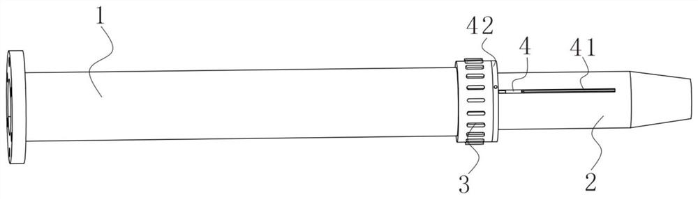
[0023] The present invention provides a technical solution: it is used for the filling tube mechanism of the down filling machine with the function of adjusting the down filling depth, please refer to figure 1 , including a down-filled outer tube 1 and a down-filled inner tube 2;

[0024] see figure 1 , figure 2 and Figure 5 , the velvet-filled inner tube 2 is slidably inserted into the inner cavity of the velvet-filled outer tube 1, and the outer wall on the right side of the velvet-filled outer tube 1 is rotated to install a threaded sleeve 3, and the threaded sleeve 3 is set on the outer wall of the velvet-filled inner tube 2, The outer wall of the velvet-filled inner tube 2 is provided with an external thread that matches the threaded sleeve 3, and the threaded sleeve 3 is fixed on the outer wall of the velvet-filled inner tube 2 by cooperating with the threaded sleeve 3 through the external thread. 3. Change the position of the threaded casing 3 on the outer wall of ...

Embodiment 2

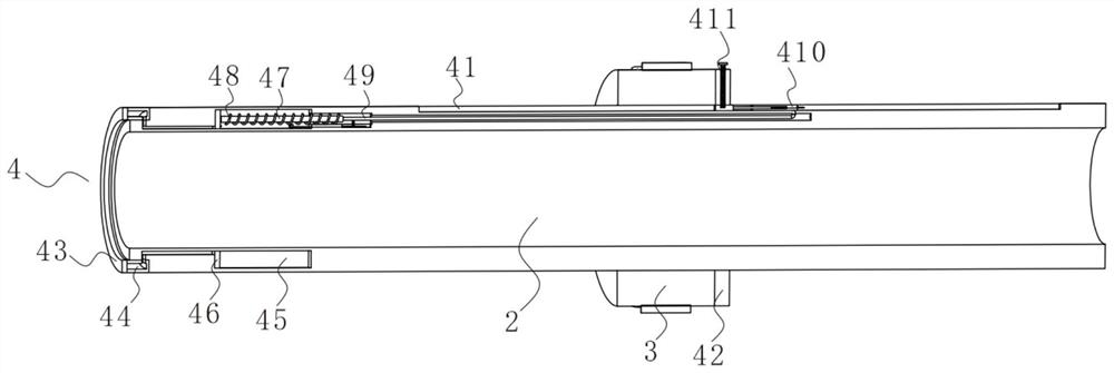
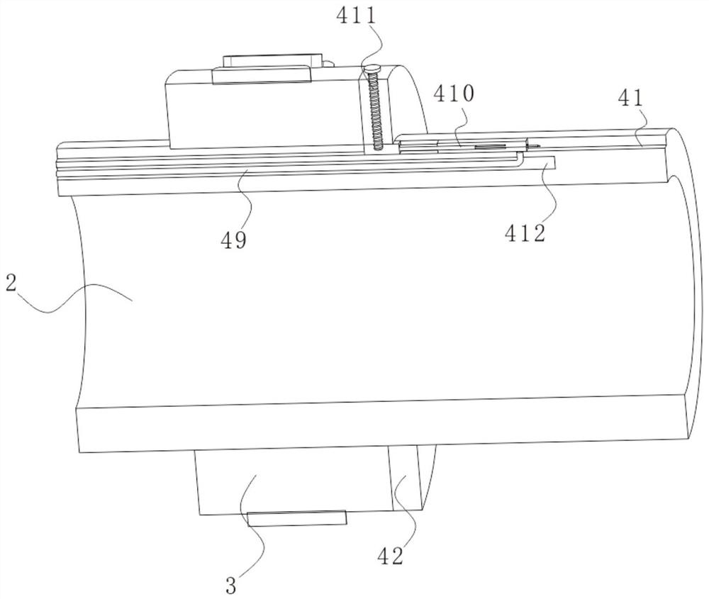
[0027] see figure 2 , image 3 and Figure 4 , on the basis of Embodiment 1, the threaded sleeve 3 right side outer wall is rotated and installed with a connecting plate 42, the connecting plate 42 is sleeved on the outer wall of the down-filled inner tube 2, and the outer wall of the top of the connecting plate 42 is screwed with a threaded rod 411, guiding Block 410 top left outer wall is provided with fixing groove 4101, and the bottom end of threaded rod 411 extends in the inner chamber of fixing groove 4101, turns threaded rod 411, and makes the bottom end of threaded rod 411 be inserted in the inner cavity of fixing groove 4101, makes connection The plate 42 is connected with the guide block 410, so that when the threaded sleeve 3 moves with the down-filled outer tube 1 to change the overall length of the down-filled tube, it will move together with the guide block 410 to trigger the adjustment device 4 and make the sealing The ring 43 is not in contact with the inside ...

Embodiment 3

[0030] see image 3 with Figure 4 , on the basis of Embodiment 2, the guide block 410 includes a connecting block 4102 that is slidably installed in the inner cavity of the guide groove 41, the fixed groove 4101 is located on the connecting block 4102, and a movable block 4103 is fixedly installed on the outer wall of the right side of the connecting block 4102. The movable block The right end of the outer wall of 4103 is slidingly sleeved with an installation sleeve 4104, and the installation sleeve 4104 is slidably installed in the inner cavity of the guide groove 41. The outer wall at the bottom of the installation sleeve 4104 is fixedly connected with the end of the stay rope 49 away from the pull rod 47, and the right side of the inner cavity of the installation sleeve 4104 runs through Plug the limiting rod 4105, the left end of the limiting rod 4105 is fixedly connected with the outer wall on the right side of the movable block 4103, the outer wall on the right side of...


PUM


Abstract

The invention discloses a down filling machine down filling pipe mechanism with a down filling depth adjusting function, and belongs to the technical field of down filling equipment. The down filling machine down filling pipe mechanism comprises a down filling outer pipe and a down filling inner pipe, the down filling inner pipe is slidably inserted into an inner cavity of the down filling outer pipe, and a threaded sleeve is rotatably mounted on the outer wall of the right side of the down filling outer pipe; the threaded sleeve is arranged on the outer wall of the down filling inner pipe in a sleeving mode, a placing groove is formed in the left end of the down filling inner pipe, an adjusting device is arranged in an inner cavity of the placing groove, in the device, a guide block is pulled rightwards, a pull rod pulls two sets of piston plates rightwards to move rightwards, air in an annular groove is drawn into an air storage groove, and the air pressure in the annular groove is reduced; a sealing ring is shrunk, the contact pressure between the sealing ring and the inner wall of the down filling outer pipe is reduced or the sealing ring does not make contact with the inner wall of the down filling outer pipe, the probability of friction between the down filling outer pipe and the sealing ring is reduced in the moving and adjusting process of the down filling outer pipe, the probability of abrasion of the sealing ring is reduced, and the probability of bending deformation of the sealing ring due to contact friction is also reduced.

Description

technical field [0001] The invention relates to the technical field of down filling equipment, in particular to a down filling tube mechanism for a down filling machine with the function of adjusting the down filling depth. Background technique [0002] When filling toys or clothing, a down filling machine is used. Generally, the object to be filled is placed on the down filling tube of the down filling machine, and the inside of the object is filled with down through the down filling tube. The convenience of using the down machine makes the down filling machine suitable for down filling processing of different depths. The existing down filling tube is generally composed of an outer tube and an inner tube. The outer tube is set on the outer wall of the inner tube, and the inner tube can be Slide on the outer wall of the down filling tube, so that the overall length of the down filling tube can be adjusted. However, in order to ensure the tightness of the down filling tube, a...

Claims


Application Information

Patent Timeline
Patent Type & Authority Applications(China)
IPC IPC(8): A41H43/00A63H9/00
CPCA41H43/00A63H9/00
Inventor 李钦
Owner 广东鸿图实业有限公司
Why Eureka
Try Eureka