Steel truss girder multi-point traction type incremental launching construction system and construction method thereof

A steel truss girder and jacking construction technology, which is applied in the direction of erecting/assembling bridges, bridges, bridge construction, etc., can solve the problems that the construction of steel truss girders cannot be carried out stably, the soil quality of the foundation does not meet the construction needs, and affects the construction speed of the project. Achieve safe and reliable installation quality, avoid excessive force on a single point, and solve the effect of high-speed traffic pressure

Pending Publication Date: 2021-11-09
ANHUI HIGHWAY BRIDGE ENG CO LTD
View PDF4 Cites 3 Cited by
  • Summary
  • Abstract
  • Description
  • Claims
  • Application Information

AI Technical Summary

Problems solved by technology

[0006] Aiming at the above-mentioned shortcomings existing in the prior art, the present invention provides a steel truss girder multi-point traction type jacking construction system and its construction method, which solves the problem that the soil quality of the foundation does not meet the construction needs, the consumption of temporary materials is large and the completion period is limited by various factors. There are many factors affecting the construction of steel truss beams that cannot be carried out stably and affect the overall construction speed of the project.

Method used


Image

  • Steel truss girder multi-point traction type incremental launching construction system and construction method thereof
  • Steel truss girder multi-point traction type incremental launching construction system and construction method thereof
  • Steel truss girder multi-point traction type incremental launching construction system and construction method thereof

Examples


Embodiment 1

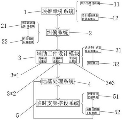
[0057] The steel truss girder multi-point traction type jacking construction system of this embodiment, such as figure 1 shown, including;

[0058] The jacking traction system 1 is used for the general traction control of the steel truss beam project, the allocation of equipment, and the subcontracting delivery of engineering tasks, including the jack general control terminal 11 and the traction strand coefficient calculation unit 12:

[0059] The jack master control terminal 11 is used to control multiple continuous jacks to move forward synchronously, to provide a power source for the steel truss beam, and to reach the design coordinates;

[0060] The traction strand coefficient calculation unit 12 is used to calculate the optimal number of traction strands, and is responsible for connecting each jack to ensure consistent operating speed;

[0061] The deviation correction system 2 is used to maintain the error and dislocation during the traction and pushing process of the m...

Embodiment 2

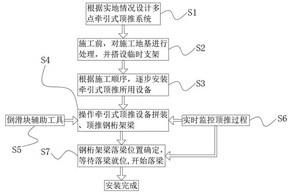
[0095] The multi-point traction type jacking construction method of the steel truss girder in the present invention comprises the following steps:

[0096] S1: The team used the multi-point traction jacking construction system to discuss and design a specific construction plan according to the actual situation at the construction site;

[0097] S2: Carry out on-site exploration of the construction site geology before construction, and carry out adaptive reinforcement treatment on it, and erect temporary supports on the surface of the reinforced foundation as required for operators to use;

[0098] S3: According to the construction sequence, install the traction-type jacking equipment on the support in sequence;

[0099] S4: Issue instructions on the control platform to control the traction jacking equipment to assemble the steel truss beams and adjust the jacking displacement;

[0100] S5: Set guide sliders on the bracket to ensure the stable operation of the traction jacking...

Embodiment 3

[0112] Such as figure 2 As shown, the formula for calculating the foundation bearing capacity of the jacking bracket is:

[0113]

[0114] In the formula: N is the maximum single pile support reaction force of 157.3T in the temporary pier during the dragging process (B, C, D temporary pier load combination 4)

[0115] Ad is the area of ​​the pole base Ad=80cm×80cm=6400cm2;

[0116] According to the consideration of the most unfavorable load, the coefficient of bearing capacity of the foundation is taken as 1.0, and the bearing capacity of the concrete foundation under the bottom support of the vertical pole is:

[0117] N / Ad=157.3×10^4 / 6.4×10^5=2.46MPa<[f]=9.5MPa, the bearing capacity of the foundation under the bottom bracket meets the requirements.

[0118] The bottom bracket is located on the 1.0mC20 concrete layer, calculated according to the force transmission area (concrete is calculated according to the divergence angle of 45 degrees, and can be fully diffused to ...


PUM


Abstract

The invention relates to the technical field of constructional engineering, in particular to a steel truss girder multi-point traction type incremental launching construction system and a construction method thereof.The steel truss girder multi-point traction type incremental launching construction system comprises an incremental launching traction system used for steel truss girder engineering traction general control, instrument allocation and sub-package type issuing of engineering tasks; The system further comprises a jack master control terminal and a traction steel strand coefficient calculation unit. The jack master control terminal is used for controlling a plurality of continuous jacks to synchronously pull and move forwards, and providing a power source for a steel truss girder to reach a design coordinate; The traction steel strand coefficient calculation unit is used for calculating the optimal number of strands of traction steel strands and is responsible for connecting each jack. The steel truss girder and the support are stressed more reasonably by adopting multi-point traction, overlarge stress of a single point is avoided. Meanwhile, the multi-point traction girder body is stable in sliding, the advancing track of the curve bridge is easier to control. The problems that the rigidity of the bottom surface of the lower chord of the steel truss girder is changed, the bearing force is not uniform, and the curved bridge pushing advancing track is not easy to control are solved.

Description

technical field [0001] The invention relates to the technical field of construction engineering, in particular to a steel truss girder multi-point traction type jacking construction system and a construction method thereof. Background technique [0002] In recent years, with the large-scale construction of expressways, steel truss bridges are more and more used in engineering construction because of their strong spanning ability, stable construction, low noise, beautiful appearance, durability, and good viewing. middle. There are more and more construction problems of steel truss beams encountered in the project. [0003] Among them, the steel truss girder jacking method is more suitable for the construction of the steel truss beam jacking method in some special environments, such as bridges crossing seas, rivers, highways, railways, and valleys. Due to the limited construction site, the jacking method is more suitable for construction. The application research of jacking m...

Claims


Application Information

Patent Timeline
Patent Type & Authority Applications(China)
IPC IPC(8): E01D21/00
CPCE01D21/00
Inventor 徐磊沈维成刘晓晗彭申凯徐先明马冲冲刘向前崔健
Owner ANHUI HIGHWAY BRIDGE ENG CO LTD
Why Eureka
Try Eureka