
Locking device and gas compressor and gas turbine comprising same

A compressor and interlocking device technology, which is applied in the field of gas turbines and compressors, can solve problems affecting the stress strength of blade roots and discs, achieve rapid installation and removal, reasonable locking structure design, and reduce the loss of aerodynamic performance.

Pending Publication Date: 2021-11-09
CHINA UNITED GAS TURBINE TECH CO LTD
View PDF2 Cites 1 Cited by
  • Summary
  • Abstract
  • Description
  • Claims
  • Application Information

AI Technical Summary

Problems solved by technology

[0007] The main purpose of the present invention is to provide a compressor rotor blade locking structure to solve the problem that the locking device in the prior art affects the stress intensity of the blade root and the disc

Method used


Image

  • Locking device and gas compressor and gas turbine comprising same
  • Locking device and gas compressor and gas turbine comprising same
  • Locking device and gas compressor and gas turbine comprising same

Examples


Embodiment 1

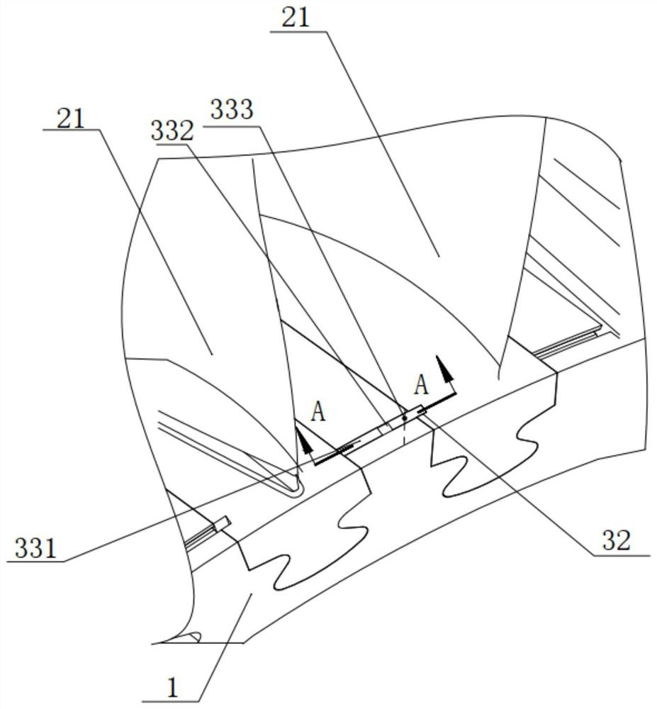
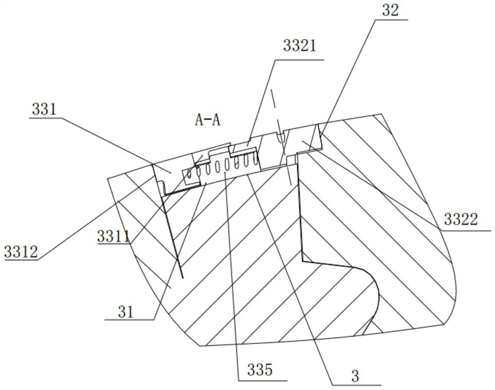
[0052] The compressor rotor blade 2 locking structure 3 provided in this embodiment includes a first installation part arranged on the wheel disk 1, a second installation part arranged on the blade root 21, and the locking structure 3 of the control blade 2 on the wheel disk 1. Interlock 33. Wherein, the interlocking device 33 is disposed between the first mounting portion and the second mounting portion, and the interlocking device 33 is operable between a locked position and an open position. In the locked position, the interlocking device 33 cooperates with the first mounting portion and the second mounting portion to limit the axial displacement of the blade 2 . That is, when in the locked position, the interlocking device 33 is locked and limited between the first installation part and the second installation part, so that the first installation part and the second installation part cannot move relative to each other, and then the blade 2 is locked on the wheel 1 superio...

Embodiment 2

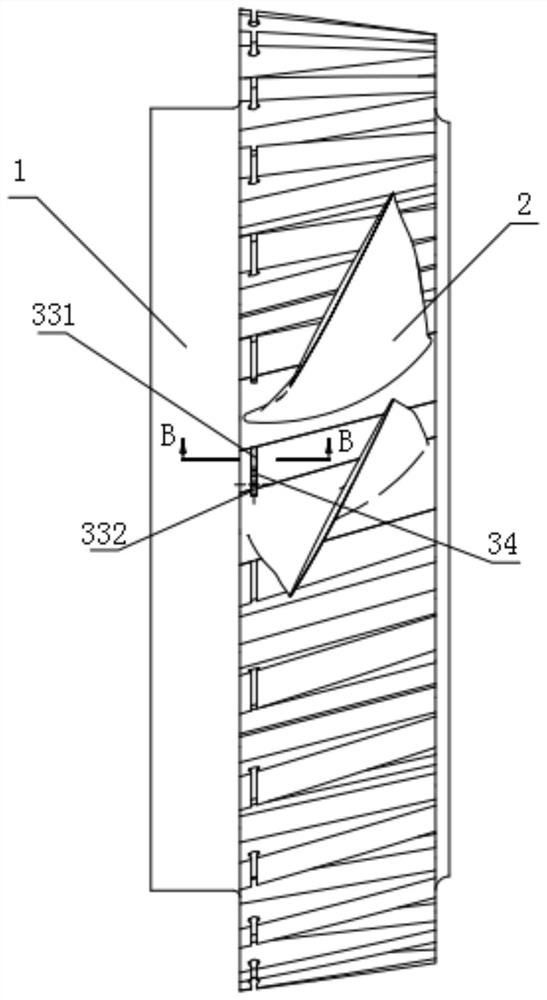
[0065] This embodiment provides a compressor and a gas turbine with the above-mentioned locking structure 3 on the basis of the above-mentioned embodiments. The compressor provided in this embodiment includes a rotor, and the rotor includes a disc 1 and blades 2 , the blade roots 21 of the blades 2 are installed on the disc 1 of the rotor, specifically arranged in the slots of the blades 2 of the disc 1 . The disc 1 is provided with a first locking groove 31 for the locking structure 3, the blade root 21 is provided with a second locking groove 32 for the locking structure 3, and the compressor also includes the locking structure as described in Embodiment 1 3.

[0066] This embodiment also provides a gas turbine with the above-mentioned compressor, and since the locking structure 3 of the compressor provided by this embodiment can reduce the impact on the strength of the compressor, it is especially suitable for heavy-duty gas turbines with higher strength requirements .

...


PUM


Abstract

The invention discloses a compressor rotor blade locking structure and a compressor and a gas turbine with the same. A rotor comprises a wheel disc and a blade, a blade root of the blade is mounted on the wheel disc of the rotor, the wheel disc is provided with a first mounting portion, the blade root is provided with a second mounting portion, and the locking structure comprises a first mounting portion, a second mounting portion and an interlocking device; and the interlocking device comprises a first sliding part, a second sliding part and an elastic part, the first sliding part and the second sliding part are arranged at the two ends of the elastic part, the interlocking device can be operated between a locking position and an opening position, and in the locking position, the interlocking device is matched with the first mounting structure and the second mounting structure to limit the axial displacement of the blade. By means of the locking device, the locking structure is arranged between the blade root and the wheel disc, and compared with the prior art that a locking device is arranged in an area between a blade root and a blade groove, where the blade root is inserted, of a wheel disc, the influence on the stress intensity of the blade root and the wheel disc is small. The contour surface of the position of the locking structure ensures the integrity of an air flow channel.

Description

technical field [0001] The invention relates to a heavy-duty gas turbine, in particular to a locking device and a compressor and a gas turbine including the locking device. Background technique [0002] A compressor usually includes a disc and blades arranged on the disc, and the rotation of the disc drives the blades on it to rotate to compress the air. Generally, blade grooves are provided on the wheel disc, and the blade roots of the blades are inserted into the blade grooves to realize the installation of the blades. And the wheel disk also needs to be provided with a locking structure to ensure that the blades are locked on the wheel disk. [0003] In the prior art, the locking structure is mainly arranged in the high-stress region between the blade root and the blade groove. For example, in the existing patent CN105927585A, there is a pin hole on the contact surface between the blade root and the rim of the impeller. Circular pin; the first half pin and the second h...

Claims


Application Information

Patent Timeline
IPC IPC(8): F04D29/34F04D29/64
CPCF04D29/322F04D29/644
Inventor 吕顺日陈虎吴宏何柳
Owner CHINA UNITED GAS TURBINE TECH CO LTD
Features
  • Generate Ideas
  • Intellectual Property
  • Life Sciences
  • Materials
  • Tech Scout
  • Unparalleled Data Quality
  • Higher Quality Content
  • 60% Fewer Hallucinations
Learn More