Safety monitoring method for heat supply pipeline

A technology for heating pipelines and safety monitoring. It is used in pipeline systems, optical fiber/cable installation, gas/liquid distribution and storage, etc. It can solve problems such as difficulty in making maintenance plans, excessive positioning accuracy errors, and difficulty in estimating the size of leaks. , to achieve the effect of short measurement period, high positioning accuracy and long measurement distance

Inactive Publication Date: 2021-11-09
CLEAN ENERGY BRANCH OF HUANENG (ZHEJIANG) ENERGY DEV CO LTD
View PDF0 Cites 0 Cited by
  • Summary
  • Abstract
  • Description
  • Claims
  • Application Information

AI Technical Summary

Problems solved by technology

For the complex structure of pipeline laying process or the change of operating conditions when adjusting pumps and valves, abnormal image features may appear in the case of no leakage, resulting in false alarms, excessive positioning accuracy errors, resulting in difficult maintenance, and It is difficult to estimate the size of the leak and make a maintenance plan, so it can only be dealt with according to the actual situation after excavation, which greatly prolongs the maintenance time and increases the maintenance cost. Therefore, the present invention provides a heating pipeline safety monitoring method, which can accurately monitor the heating Real-time monitoring of pipeline safety

Method used


Image

  • Safety monitoring method for heat supply pipeline
  • Safety monitoring method for heat supply pipeline
  • Safety monitoring method for heat supply pipeline

Examples


Embodiment Construction

[0034] The technical solutions in the embodiments of the present invention will be clearly and completely described below in conjunction with the accompanying drawings in the embodiments of the present invention. Obviously, the described embodiments are only some of the embodiments of the present invention, not all of them. Based on The embodiments of the present invention and all other embodiments obtained by persons of ordinary skill in the art without making creative efforts belong to the protection scope of the present invention.

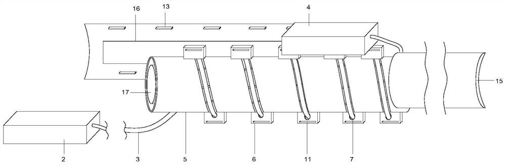
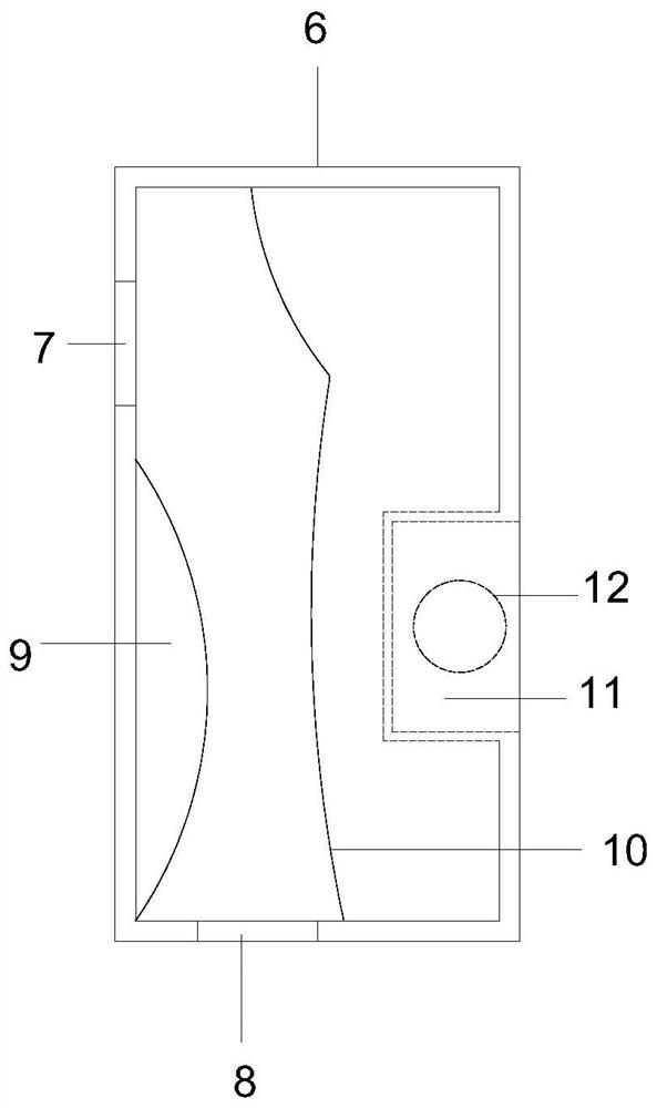
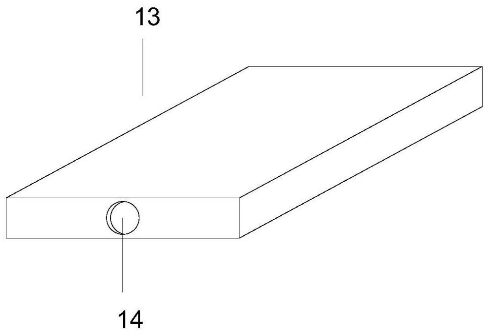
[0035] see Figure 1-6 , the present invention provides a heating pipeline safety monitoring method, the steps are as follows;

[0036] Pass the temperature-sensing optical cable through the No. 1 and No. 2 slots of the protective plate in turn, so that the temperature-sensing optical cable is spirally wound on the outer casing, and then insert the connecting plate on the outer outer plate into the protective plate correspondingly In the connec...


PUM


Abstract

The invention discloses a safety monitoring method for a heat supply pipeline. The method comprises the steps: enabling a temperature-sensing optical cable to sequentially pass through a first through groove and a second through groove of a protection plate, enabling the temperature-sensing optical cable to be wound on an outer sleeve in a spiral manner, enabling a connection plate on the outer sleeve to be correspondingly inserted into a connection groove of the protection plate until a fixing groove is aligned with an insertion groove, and enabling a bolt to be inserted into the fixing groove and the insertion groove to form threaded connection among the bolt, the fixing groove and the insertion groove. The temperature-sensing optical cable penetrates through the protection plate and is protected and fixed through the outer sleeve, the temperature-sensing optical cable can make full contact with the outer sleeve effectively, the temperature sensing optical cable is spirally wound around the outer sleeve, the contact area of the temperature sensing optical cable and the outer sleeve can be increased, and then the temperature of the surface of the outer sleeve can be monitored more comprehensively; therefore, the monitoring range is wider, the monitoring is more accurate, and the situation that the heat supply pipeline is broken and is not known due to the fact that monitoring is not in place due to the fact that the contact area of the temperature-sensing optical cable is too limited in the prior art is avoided.

Description

technical field [0001] The invention relates to the technical field of heating pipeline safety monitoring, in particular to a heating pipeline safety monitoring method. Background technique [0002] In the prior art, a thermal pipeline is a pipeline for transporting thermal energy medium such as steam or superheated water. After years of urban transformation, thermal pipelines in large and medium-sized cities mostly adopt underground laying, including pipe trench laying and direct burial laying. Thermal pipelines will be subjected to high temperature, wear, physical and chemical effects during use, coupled with the disturbance of surrounding underground engineering construction and ground traffic dynamic loads, thermal pipelines will gradually produce defects such as cracks, deformation, and joint damage, and then evolve into fractures, Accidents such as water leakage. During the heating period, if a large amount of water leaks or even breaks in the pipeline, due to the hi...

Claims


Application Information

Patent Timeline
Patent Type & Authority Applications(China)
IPC IPC(8): F17D5/02F17D5/00G02B6/46
CPCF17D5/02F17D5/00G02B6/46
Inventor 沈小飞周波谢勇潘健林定君曹德华
Owner CLEAN ENERGY BRANCH OF HUANENG (ZHEJIANG) ENERGY DEV CO LTD
Why Eureka
Try Eureka