Intelligent monitoring alarm device for equipment operation personification inspection
A technology for intelligent monitoring and equipment operation. It is applied to fire alarms that rely on smoke/gas effects, inspection time patrols, etc. It can solve problems such as reduced practicability, poor sensitivity, and ability to affect continuous use, reducing labor costs. , the effect of improving the chance of escape and improving the stability
- Summary
- Abstract
- Description
- Claims
- Application Information
AI Technical Summary
Problems solved by technology
Method used
Image

Examples
Embodiment 1
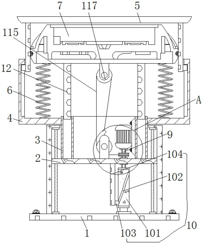
[0027] see figure 1 , 5 6. An intelligent monitoring and alarm device for anthropomorphic inspection of equipment operation, including a retractable assembly 11, a ratchet 111 is provided inside the retractable assembly 11, and a groove matching the outer wall of the flower shaft 9 is provided inside the ratchet 111, The outer wall of the flower shaft 9 is inserted into the inside of the ratchet 111, the left side of the outer wall of the ratchet 111 is clamped with movable teeth 112, the back of the movable teeth 112 is riveted with a rotating disc 113, and the front of the rotating disc 113 is provided with an arc-shaped chute 114, the inside of the rotating disk 113 is provided with no less than four arc-shaped chute 114, the left side of the movable tooth 112 is engaged with the bottom of the inside of the arc-shaped chute 114, and the outer wall of the rotating disk 113 is fixedly connected with a pull cord 115 , the top of the pull cord 115 is slidably connected to the ...
Embodiment 2
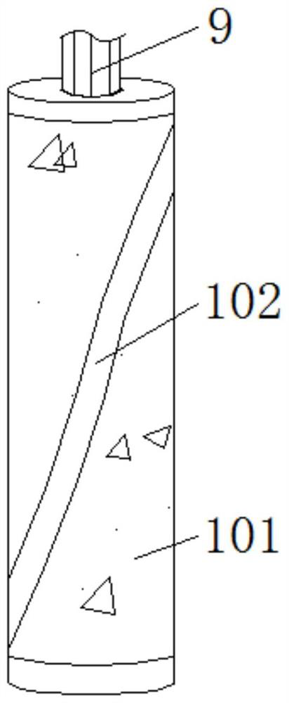
[0031] see Figure 1-4 , an intelligent monitoring and alarm device for anthropomorphic inspection of equipment operation, including a lifting assembly 10, a rotating column 101 is arranged inside the lifting assembly 10, the bottom of the flower shaft 9 is inserted into the inside of the rotating column 101, and the inside of the rotating column 101 There is a groove matching the outer wall of the flower shaft 9, and the outer wall of the rotating column 101 is provided with an annular chute 102. The annular chute 102 is a ring structure connected end to end. Block 103, the left side of sliding block 103 is welded with support bar 104, and the top of support bar 104 is welded on the bottom of sliding circular plate 2.
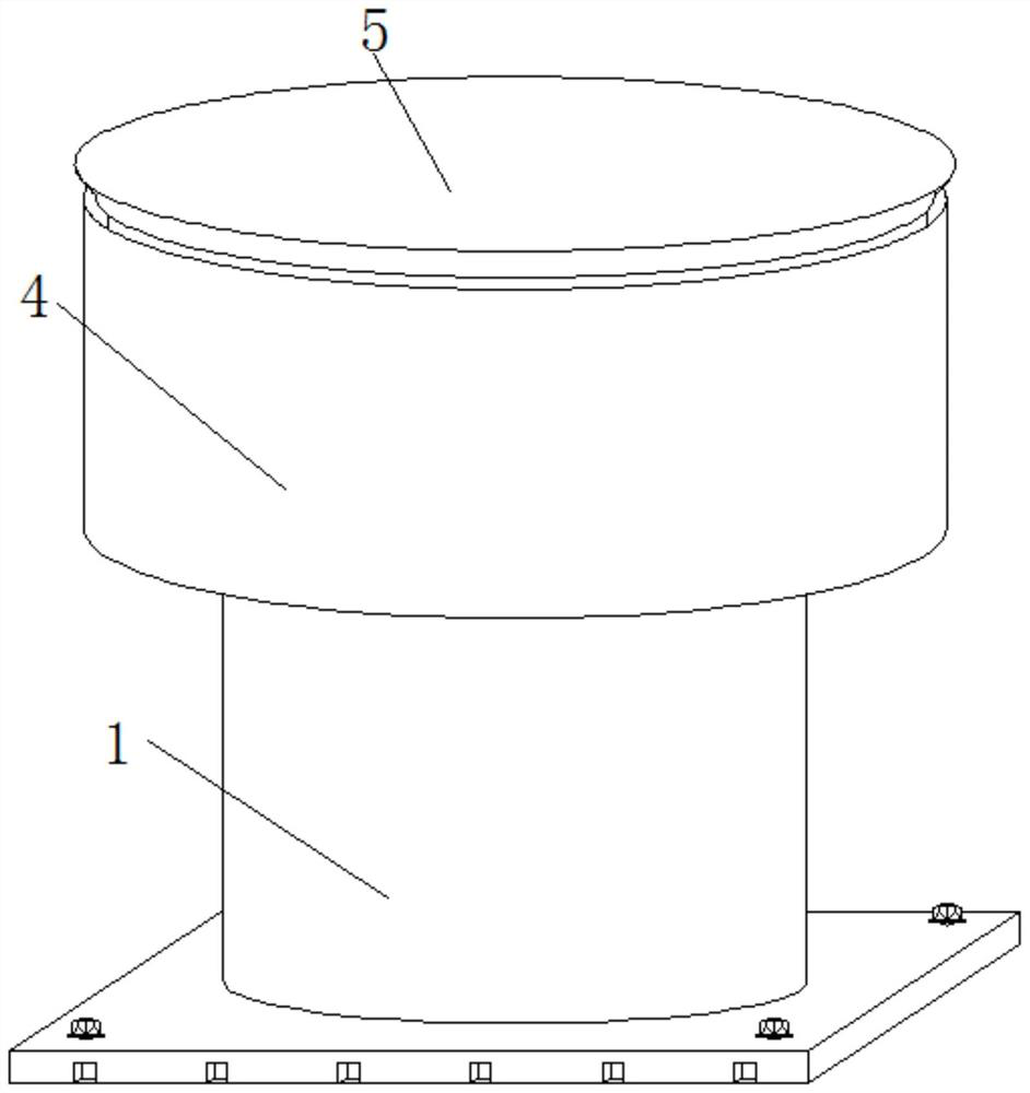
[0032] It also includes a fixed cylinder base 1, the inside of the fixed cylinder base 1 is slidably connected with a sliding circular plate 2, the top of the sliding circular plate 2 is welded with a chute 3, the outer wall of the chute 3 is welded with a lif...
Embodiment 3
[0035] see Figure 1-6 , an intelligent monitoring and alarm device for anthropomorphic inspection of equipment operation, including a shrinking assembly 11, a ratchet 111 is arranged inside the shrinking assembly 11, and a groove matching the outer wall of the flower shaft 9 is arranged inside the ratchet 111, and the flower shaft The outer wall of 9 is inserted into the inside of the ratchet 111, the left side of the outer wall of the ratchet 111 is clamped with movable teeth 112, the back of the movable teeth 112 is riveted with a rotating disk 113, and the front of the rotating disk 113 is provided with an arc-shaped chute 114, The inside of the rotating disk 113 is provided with no less than four arc-shaped chute 114, the left side of the movable tooth 112 is engaged with the bottom of the inside of the arc-shaped chute 114, and the outer wall of the rotating disk 113 is fixedly connected with a pull cord 115. The top of the rope 115 is slidably connected to the steering ...
PUM
 Abstract
Description
Claims
Application Information