
Stripping device for safe work on cable skins in electrical equipment

A technology for electrical equipment and safe operation, which is applied to cable installation devices, cable installation, and equipment for dismantling/armored cables, etc. It can solve the problems of inconvenient cable loop cutting, large damage to cable appearance, and lack of adjustment and control functions. , to achieve the effect of convenient repair or transfer and consistent cutting depth

Active Publication Date: 2021-12-21
南通丞贝科技有限公司
View PDF4 Cites 0 Cited by
  • Summary
  • Abstract
  • Description
  • Claims
  • Application Information

AI Technical Summary

Problems solved by technology

[0006] The purpose of the present invention is to provide a stripping device for electrical equipment to carry out safe operations on the cable skin, to solve the problem that the currently used stripping method proposed in the above-mentioned background technology causes great damage to the cable appearance, and does not have the ability to perform ring cutting. The guide ring cutting function to avoid the inclination of the cut is inconvenient to directly ring the cable outside the cable that cannot be threaded, and it does not have the adjustment control function to stably control the ring cutting depth, which is not conducive to the problem of rapid stripping

Method used


Image

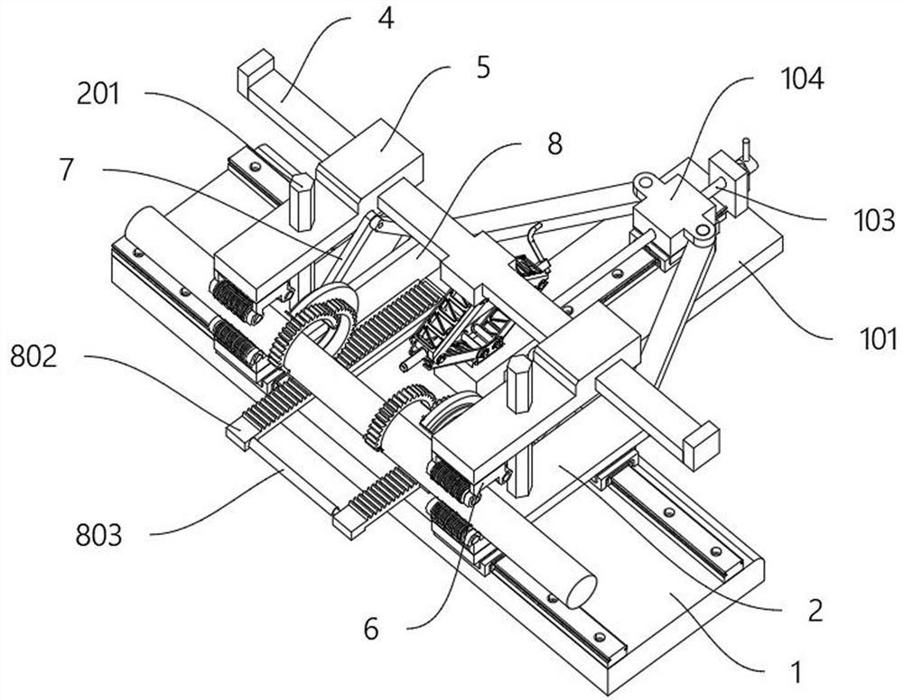
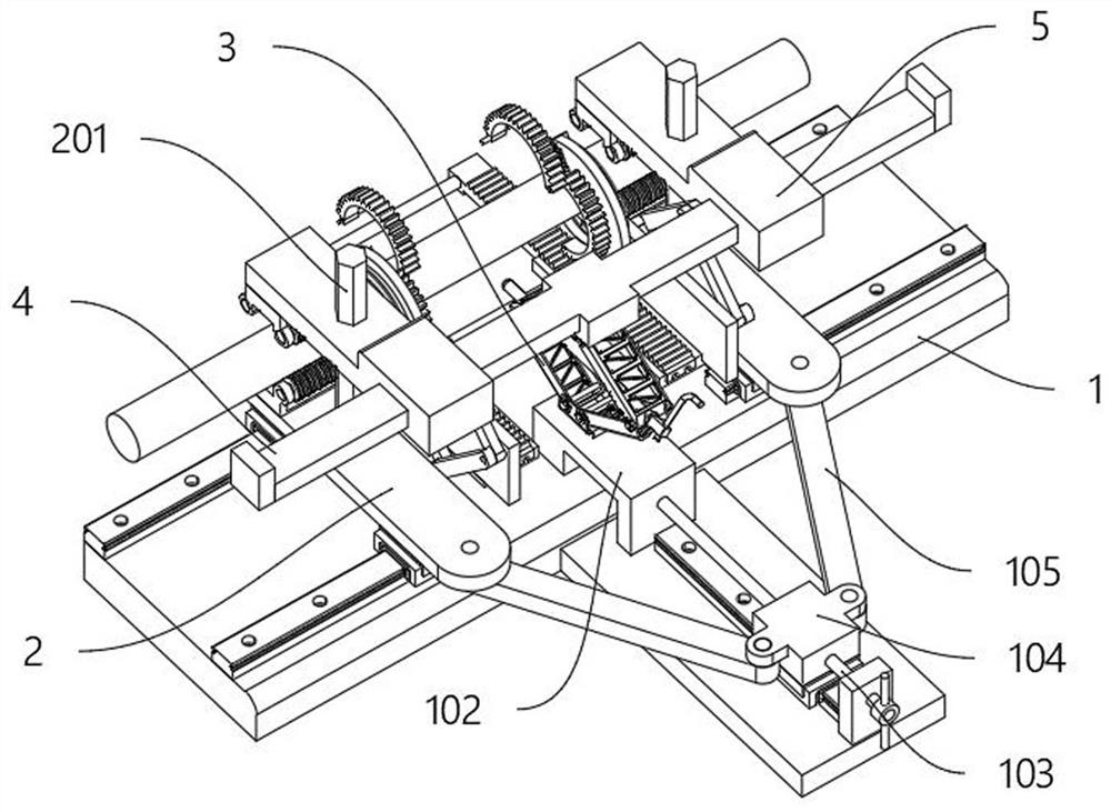
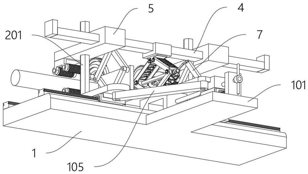
  • Stripping device for safe work on cable skins in electrical equipment
  • Stripping device for safe work on cable skins in electrical equipment
  • Stripping device for safe work on cable skins in electrical equipment

Examples


Embodiment Construction

[0031] The following will clearly and completely describe the technical solutions in the embodiments of the present invention with reference to the accompanying drawings in the embodiments of the present invention. Obviously, the described embodiments are only some, not all, embodiments of the present invention.

[0032] In the description of the present invention, unless otherwise stated, the meaning of "plurality" is two or more; the terms "upper", "lower", "left", "right", "inner", "outer" , "front end", "rear end", "head", "tail", etc. indicate the orientation or positional relationship based on the orientation or positional relationship shown in the drawings, and are only for the convenience of describing the present invention and simplifying the description, rather than Nothing indicating or implying that a referenced device or element must have a particular orientation, be constructed, and operate in a particular orientation should therefore not be construed as limiting ...


PUM


Abstract

The invention discloses a stripping device used for electrical equipment to perform safe operations on the cable skin, relates to the technical field of cable insulation, and solves the problem that the currently used stripping method causes relatively large damage to the cable surface, and does not have the ability to avoid ring cutting. Issue with guide circumcision functionality with slanted cutouts. The stripping device used for electrical equipment to safely work on the cable skin includes a base, the middle and rear side of the base is integrally provided with a convex plate, and the middle bridge is integrally provided in the middle of the top of the base and the convex plate, and the intermediate bridge The rear side is rotatably provided with a lead screw, and the top of the rear end of the convex plate is provided with a frame body that is rotatably connected with the rear end of the lead screw. The split ring is provided to provide a circumcision function for the stripping device, and the fixed half ring gear is fixed by a ball pin. Combined with the movable half-gear buckle to form a ring-shaped full-gear structure, the L-shaped blade can be used to cut the outer part of the cable as a whole, which is more stable and tidy than the cutting method currently used.

Description

technical field [0001] The invention relates to the technical field of cable insulation removal, in particular to a stripping device used for electrical equipment to perform safe operations on the cable skin. Background technique [0002] When the cable is being repaired or transferred, it is necessary to peel off the outer skin of the cable. At present, the commonly used method is manual ring cutting, which needs to cut the skin vertically and horizontally and then remove the skin, or directly use tools such as wire strippers. cut. [0003] The currently used stripping method causes great damage to the appearance of the cable. It does not have the function of guiding ring cutting to avoid the inclination of the cut when ring cutting. It is inconvenient to directly ring the cable outside the cable that cannot be threaded. It does not have a stable control ring. The adjustment control function of cutting depth is not conducive to quick stripping. [0004] Therefore, the exi...

Claims


Application Information

Patent Timeline
Patent Type & Authority Patents(China)
IPC IPC(8): H02G1/12
CPCH02G1/1265H02G1/127
Inventor 杨海林
Owner 南通丞贝科技有限公司
Learn More