A cargo handling device
A technology for handling devices and goods, applied in the direction of transportation and packaging, load hanging components, etc., can solve the problems of cumbersome hook operation, high safety risks, and affecting work efficiency, and achieve the effect of convenient operation process
- Summary
- Abstract
- Description
- Claims
- Application Information
AI Technical Summary
Problems solved by technology
Method used
Image
Examples
Embodiment 1
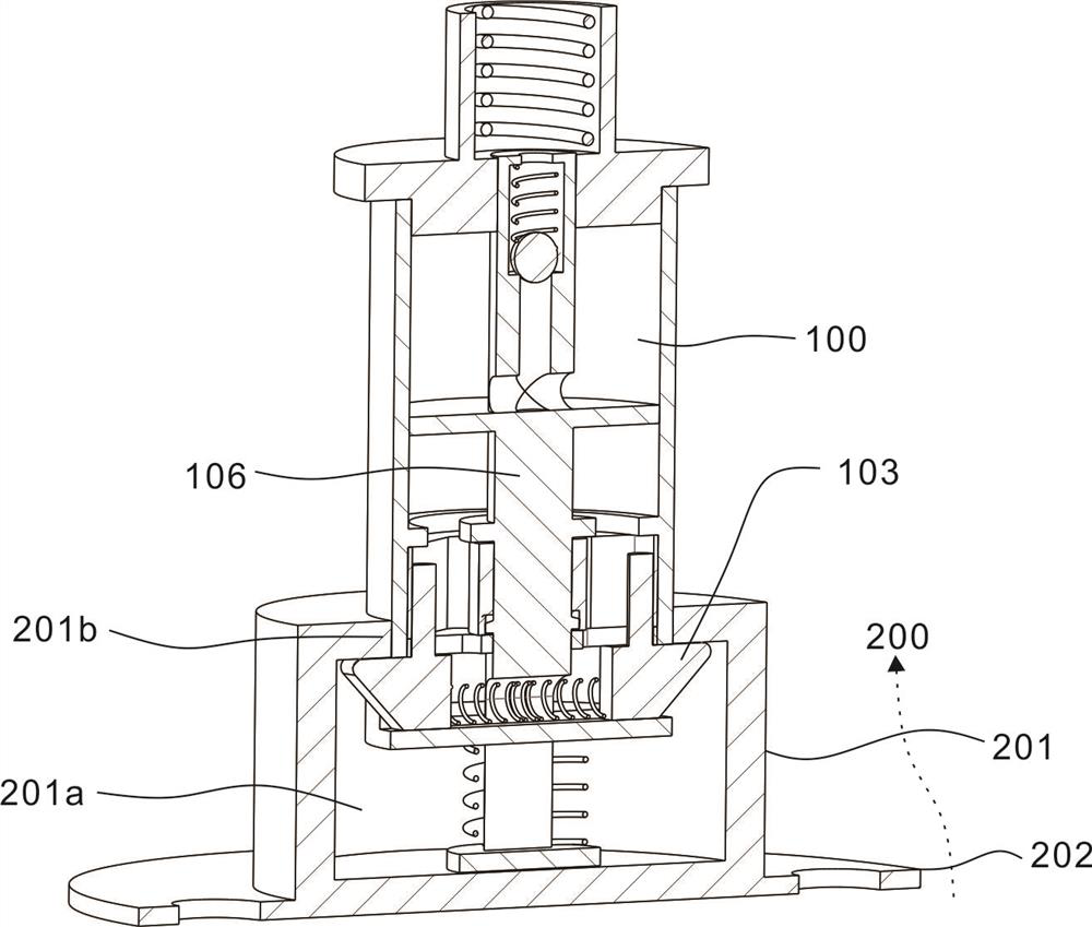
[0028] This embodiment provides a cargo handling device, which includes a picking unit 100 and a fixing unit 200 .
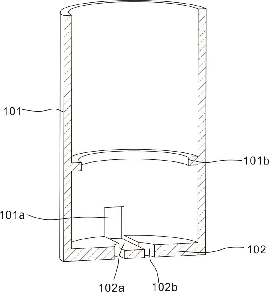
[0029] refer to figure 1 , figure 2 , the extraction unit 100 includes an extraction cylinder 101, the extraction cylinder 101 is cylindrical, the interior of the extraction cylinder 101 is provided with a cylindrical cavity, the bottom of the extraction cylinder 101 is provided with a bottom plate 102, and two through grooves 101a are symmetrically arranged on the side wall of the extraction cylinder 101 The slot 101a is provided with a block 103, two blocks 103 are arranged symmetrically, the block 103 can move radially in the slot 101a, and the moving directions of the two blocks 103 are opposite.
[0030] refer to figure 1 , the fixing unit 200 includes a fixing block 201 and a flange 202 connected to the lower end of the fixing block 201 . The flange plate 202 is fixed on the goods to be transported, and the fixing here can be through but not limited to...
Embodiment 2
[0035] The embodiment is based on the previous embodiment, and the difference from the previous embodiment is that in this embodiment, after the goods are lifted and transported to the designated location, the goods can be dropped off again for the next transport. The specific structure of this embodiment is as follows.
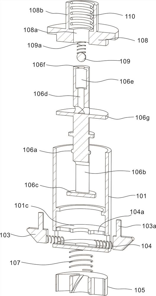
[0036] combine image 3A partition 101c is arranged inside the extracting cylinder 101, and the clamping block 103 is located between the partition 101c and the bottom plate 102 to prevent tilting. The partition 101c is provided with two long slots 104a in the radial direction, and the block 103 is provided with a pin shaft 103a extending axially along the extraction cylinder 101, and the pin shaft 103a passes through the corresponding long slots 104a. The position of the block 103 is adjusted by controlling the pin shaft 103a.
[0037] combine image 3 , Figure 4 A turntable 105 is connected above the partition 101c, the turntable 105 is disc-shaped, an...
Embodiment 3
[0041] The embodiment is based on the previous embodiment, and the difference from the previous embodiment is that this embodiment includes a transmission rod 106 arranged in the extracting cylinder 101 to drive the movement of the turntable 105 .
[0042] refer to image 3 , Figure 4 , the turntable 105 is provided with a first through hole 105e, the transmission rod 106 passes through the first through hole 105e and the partition 101c, the inner wall of the first through hole 105e is provided with a spiral groove 105f along the helical line, and the transmission rod 106 is provided with The protrusion 106a is inserted into the spiral groove 105f, and the axial movement of the transmission rod 106 can be transformed into the rotation of the turntable 105 .
[0043] refer to figure 2 , image 3 , in order to provide installation space for the first spring 104, the end of the transmission rod 106 close to the bottom plate 102 is provided with an avoidance groove 106b, and ...
PUM
 Abstract
Description
Claims
Application Information
 - R&D
- Intellectual Property
- Life Sciences
- Materials
- Tech Scout
- Unparalleled Data Quality
- Higher Quality Content
- 60% Fewer Hallucinations
Browse by: Latest US Patents, China's latest patents, Technical Efficacy Thesaurus, Application Domain, Technology Topic, Popular Technical Reports.
© 2025 PatSnap. All rights reserved.Legal|Privacy policy|Modern Slavery Act Transparency Statement|Sitemap|About US| Contact US: help@patsnap.com


