Self-priming non-clogging diaphragm pump

A non-clogging, diaphragm pump technology, used in pumps, pumps with flexible working elements, liquid variable-capacity machines, etc., can solve the problems of diaphragm damage, affecting the effect of pump liquid, and clogging of the liquid inlet port, to avoid excessive damage effect

Active Publication Date: 2021-11-12
SHENZHEN DEYUXIN TECH CO LTD
View PDF6 Cites 0 Cited by
  • Summary
  • Abstract
  • Description
  • Claims
  • Application Information

AI Technical Summary

Problems solved by technology

[0003] The self-priming diaphragm pump commonly used in the prior art is provided with a diaphragm on one side of the pump liquid pipeline, and the diaphragm is reciprocated to both sides by electric, pneumatic or hydraulic power from the other side of the diaphragm, so that the pump liquid The air pressure at the position of the diaphragm changes reciprocatingly from the tube to the diaphragm, and the liquid ente

Method used


Image

  • Self-priming non-clogging diaphragm pump
  • Self-priming non-clogging diaphragm pump
  • Self-priming non-clogging diaphragm pump

Examples


Embodiment 1

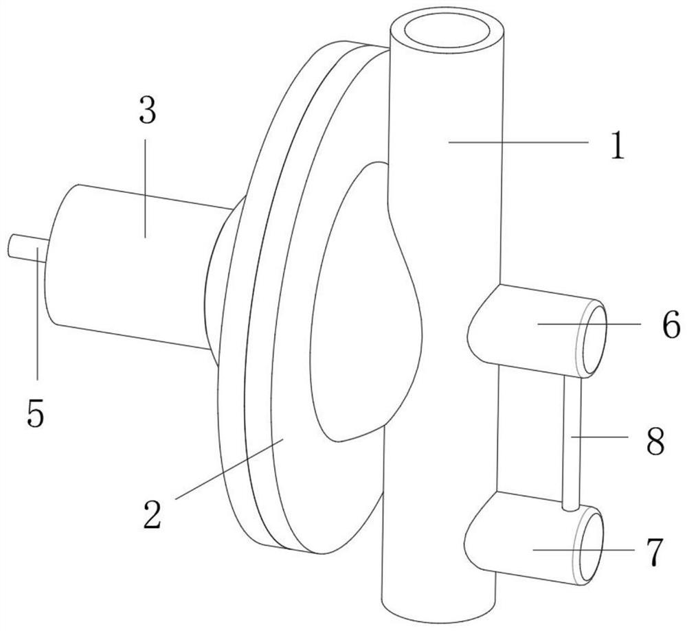
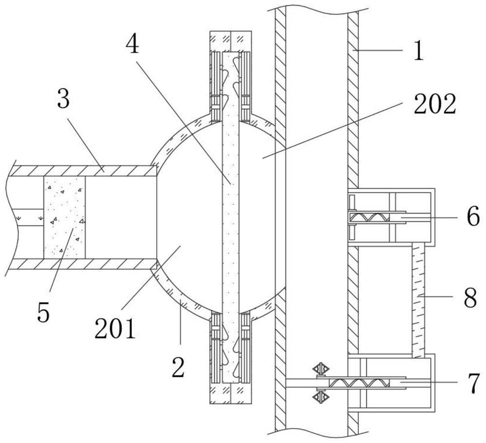
[0030] refer to figure 1 and figure 2 , a self-priming non-clogging diaphragm pump, including a pump liquid pipe 1, a diaphragm seat 2 and a fixed pipe 3 connected in sequence, a diaphragm 4 is fixed in the middle of the diaphragm seat 2, and a movable column is arranged in the fixed pipe 3 The plug 5, the side of the diaphragm 4 close to the movable plunger 5 in the diaphragm seat 2 is set as the driving cavity 201, and the side of the diaphragm 4 in the diaphragm seat 2 close to the pump liquid pipe 1 is set as the pump liquid chamber 202, and the pump liquid pipe 1 A first piston mechanism 6 is provided on the outer wall corresponding to the pump liquid chamber 202, and a second piston mechanism 7 is installed on the outer wall of the pump liquid pipe 1 close to the opening of the liquid inlet. The first piston mechanism 6 and the second piston mechanism 7 There is a connecting pipe 8 connected between them. Actually, when using this equipment to pump liquid, the diaphrag...

Embodiment 2

[0032] refer to figure 1 and figure 2, a self-priming non-clogging diaphragm pump, including a pump liquid pipe 1, a diaphragm seat 2 and a fixed pipe 3 connected in sequence, a diaphragm 4 is fixed in the middle of the diaphragm seat 2, and a movable movable pipe is arranged in the fixed pipe 3 The plunger 5, the side of the diaphragm 4 close to the movable plunger 5 in the diaphragm seat 2 is set as the driving cavity 201, and the side of the diaphragm 4 in the diaphragm seat 2 close to the pump liquid tube 1 is set as the pump liquid chamber 202, and the pump liquid A first piston mechanism 6 is provided on the outer wall of the tube 1 corresponding to the pump liquid chamber 202, and a second piston mechanism 7 is installed on the outer wall of the pump liquid tube 1 close to the opening of the liquid outlet. The first piston mechanism 6 and the second piston mechanism 7 is connected with a communication pipe 8, and the second piston mechanism 7 is used to dredge the liq...

Embodiment 3

[0034] A self-priming non-clogging diaphragm pump, including a pump liquid pipe 1, a diaphragm seat 2 and a fixed pipe 3 connected in sequence, a diaphragm 4 is fixed in the middle of the diaphragm seat 2, and a movable column is arranged in the fixed pipe 3 The plug 5, the side of the diaphragm 4 close to the movable plunger 5 in the diaphragm seat 2 is set as the driving cavity 201, and the side of the diaphragm 4 in the diaphragm seat 2 close to the pump liquid pipe 1 is set as the pump liquid chamber 202, and the pump liquid pipe 1. A first piston mechanism 6 is provided at the position corresponding to the pump liquid cavity 202 on the outer wall, and a second piston mechanism 7 is provided on the outer wall of the pump liquid pipe 1 at the positions where the liquid inlet and the liquid outlet are opened. The first piston mechanism 6 and the A connecting pipe 8 is connected between the two second piston mechanisms 7, so that the change of the diaphragm 4 is used to dredge...


PUM


Abstract

The invention belongs to the technical field of diaphragm pumps, and particularly relates to a self-priming non-clogging diaphragm pump. According to the scheme, the pump comprises a liquid pumping pipe, a diaphragm seat and a fixed pipe which are communicated in sequence, wherein a diaphragm is fixed to the middle of the diaphragm seat; a movable plunger is arranged in the fixed pipe and can move; a driving cavity is formed in the side, close to the movable plunger, of the diaphragm in the diaphragm seat; a liquid pumping cavity is formed in the side, close to the liquid pumping pipe, of the diaphragm in the diaphragm seat; a first piston mechanism is arranged at the position, corresponding to the liquid pumping cavity, of the outer wall of the liquid pumping pipe; a second piston mechanism is arranged at the end of the outer wall of the liquid pumping pipe; and a communicating pipe is connected between the first piston mechanism and the second piston mechanism. The air pressure change driven by the diaphragm is effectively utilized to dredge the liquid inlet end, so that the liquid inlet end is effectively prevented from being clogged to affect the whole liquid pumping operation, and excessive damage to the diaphragm due to suction of the diaphragm position is effectively avoided.

Description

technical field [0001] The invention relates to the technical field of diaphragm pumps, in particular to a self-priming non-clogging diaphragm pump. Background technique [0002] The diaphragm pump is actually an embolism pump, which separates the infused liquid from the live column and the pump cylinder by means of a thin film, thereby protecting the live column and the pump cylinder. By receiving the control signal output by the adjustment control unit, the fluid flow is changed by means of power operation. It is often used to transport relatively viscous slurry. [0003] The self-priming diaphragm pump commonly used in the prior art is provided with a diaphragm on one side of the pump liquid pipeline, and the diaphragm is reciprocated to both sides from the other side of the diaphragm through electric, pneumatic or hydraulic power, so that the pump liquid The air pressure at the position of the diaphragm changes reciprocatingly from the pipe to the diaphragm, and the liq...

Claims


Application Information

Patent Timeline
IPC IPC(8): F04B43/067F04B43/00
CPCF04B43/067F04B43/0009
Inventor 冯银涛
Owner SHENZHEN DEYUXIN TECH CO LTD
Why Eureka
Try Eureka