Multi-temperature processing

Inactive Publication Date: 2008-04-29
FLAMM DANIEL L
View PDF35 Cites 6 Cited by
  • Summary
  • Abstract
  • Description
  • Claims
  • Application Information

AI Technical Summary

Benefits of technology

[0009]The present invention provides a technique, including a method and apparatus, for fabricating a product using a plasma discharge. One aspect of the present technique relies upon multi-stage etching processes for selectively removing a film on a workpiece using differing temperatures. It overcomes serious disadvantages of prior art methods in which throughput and etching rate were lowered in order to avoid excessive device damage to a workpiece. In particular, this technique is extremely beneficial for removing resist masks which have been used to effect selective ion implantation of a substrate in some embodiments. In general, implantation of ions into a resist masking surface causes the upper surface of said resist to become extremely cross-linked and contaminated by materials from the ion bombardment. If the cross-linked layer is exposed to excessive temperature, it is prone to rupture and forms contaminative particulate matter. Hence, the entire resist layer is often processed at a low temperature to avoid this particle problem. Processing at a lower temperature often requires excessive time which lowers throughput. Accordingly, the present invention overcomes these disadvantages of conventional processes by rapidly removing a majority of resist at a higher temperature after an ion implanted layer is removed without substantial particle generation at a lower temperature.
[0010]In another aspect, the present invention provides a process which utilizes temperature changes to achieve high etch rates while simultaneously maintaining high etch selectivity between a layer which is being pattered or removed other material layers. An embodiment of this process advantageously employs a sequence of temperature changes as an unexpected means to avoid various types of processing damage to the a device and material layers. A novel inventive means for effecting a suitable controlled change in temperature as part of a process involves the use of a workpiece support which has low thermal mass in comparison to the heat transfer means. In an aspect of this invention, a fluid is utilized to change the temperature of a workpiece. In another aspect, the thermal capacity of a circulating fluid is sufficiently greater than the thermal capacity of the workpiece support that it permits maintaining the workpiece at a substantially uniform temperature.
[0011]Still another aspect of the invention provides an apparatus for etching a substrate in the manufacture of a device using different temperatures during etching. The apparatus includes a chamber and a substrate holder disposed in the chamber. The substrate holder has a selected thermal mass to facilitate changing the temperature of the substrate to be etched. That is, the selected thermal mass of the substrate holder allows for a change from a first temperature to a second temperature within a characteristic time period to process a film. The present apparatus can, for example, provide different processing temperatures during an etching process or the like.

Problems solved by technology

In general, implantation of ions into a resist masking surface causes the upper surface of said resist to become extremely cross-linked and contaminated by materials from the ion bombardment.
If the cross-linked layer is exposed to excessive temperature, it is prone to rupture and forms contaminative particulate matter.
Processing at a lower temperature often requires excessive time which lowers throughput.

Method used


Image

  • Multi-temperature processing
  • Multi-temperature processing
  • Multi-temperature processing

Examples


Embodiment Construction

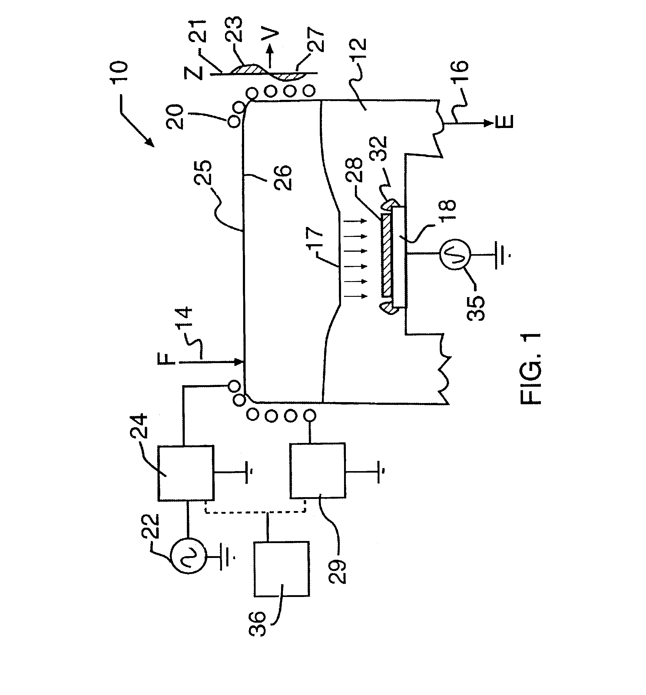
[0023]FIG. 1 is a simplified diagram of a plasma etch apparatus 10 according to the present invention. This etch apparatus is provided with an inductive applicator, e.g., inductive coil. This etch apparatus depicted, however, is merely an illustration, and should not limit the scope of the claims as defined herein. One of ordinary skilled in the art may implement the present invention with other treatment chambers and the like.

[0024]The etch apparatus includes a chamber 12, a feed source 14, an exhaust 16, a product support check or pedestal 18, an inductive applicator 20, a radio frequency (“rf”) power source 22 to the inductive applicator 20, wave adjustment circuits 24, 29 (WACs), a radio frequency power source 35 to the pedestal 18, a controller 36, an agile temperature control means 19 , and other elements. Optionally, the etch apparatus includes a gas distributor 17.

[0025]The chamber 12 can be any suitable chamber capable of housing a product 28, such as a wafer to be etched, ...


PUM

PropertyMeasurementUnit
Temperatureaaaaaaaaaa

Abstract

The present invention provides a technique, including a method and apparatus, for etching a substrate in the manufacture of a device. The apparatus includes a chamber and a substrate holder disposed in the chamber. The substrate holder has a selected thermal mass to facilitate changing the temperature of the substrate to be etched during etching processes. That is, the selected thermal mass of the substrate holder allows for a change from a first temperature to a second temperature within a characteristic time period to process a film. The present technique can, for example, provide different processing temperatures during an etching process or the like.

Description

CROSS-REFERENCE TO RELATED APPLICATIONS[0001]This present application is a continuation-in-part of U.S. application Ser. No. 60 / 058,650 filed Sep. 11, 1997, and a continuation-in-part of U.S. application Ser. No. 08 / 567,224 filed Dec. 4, 1995, now abandoned which are hereby incorporated by reference for all purposes.BACKGROUND OF THE INVENTION[0002]This invention relates generally to plasma processing. More particularly, one aspect of the invention is for greatly improved plasma processing of devices using an in-situ temperature application technique. Another aspect of the invention is illustrated in an example with regard to plasma etching or resist stripping used in the manufacture of semiconductor devices. The invention is also of benefit in plasma assisted chemical vapor deposition (CVD) for the manufacture of semiconductor devices. But it will be recognized that the invention has a wider range of applicability. Merely by way of example, the invention also can be applied in othe...

Claims


Application Information

Patent Timeline
IPC IPC(8): H05H1/00H01L21/302H01J37/32H05H1/46
CPCH01J37/321H01J37/32174H05H1/46
Inventor FLAMM, DANIEL L.
Owner FLAMM DANIEL L
Why Eureka
Try Eureka