Semi-rigid node test device with adjustable rigidity

A test device, a semi-rigid technology, applied in the direction of measuring device, strength characteristics, using stable tension/pressure test material strength, etc., can solve the problems that cannot simulate the constraints of the joints at both ends of the test member, and the force situation does not match.

Active Publication Date: 2021-11-12
SOUTHWEST ELECTRIC POWER DESIGN INST OF CHINA POWER ENG CONSULTING GROUP CORP
View PDF18 Cites 0 Cited by
  • Summary
  • Abstract
  • Description
  • Claims
  • Application Information

AI Technical Summary

Problems solved by technology

[0003] The purpose of the present invention is to provide a semi-rigid joint test device with adjustable stiffness to solve the problem that the existing test device uses a knife-edge hinge to simulate the hinges at both ends of the test member, but the angle of the knife-edge hinge cannot be constrained, and the test member deforms under compression. Afterwards, there will be free deflection without constraints, which is inconsistent with the actual force of the tower, so the device cannot simulate the problem that the nodes at both ends of the test member are constrained

Method used


Image

  • Semi-rigid node test device with adjustable rigidity
  • Semi-rigid node test device with adjustable rigidity

Examples


Embodiment 1

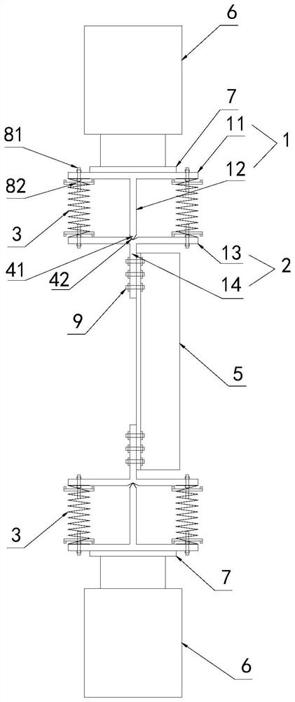
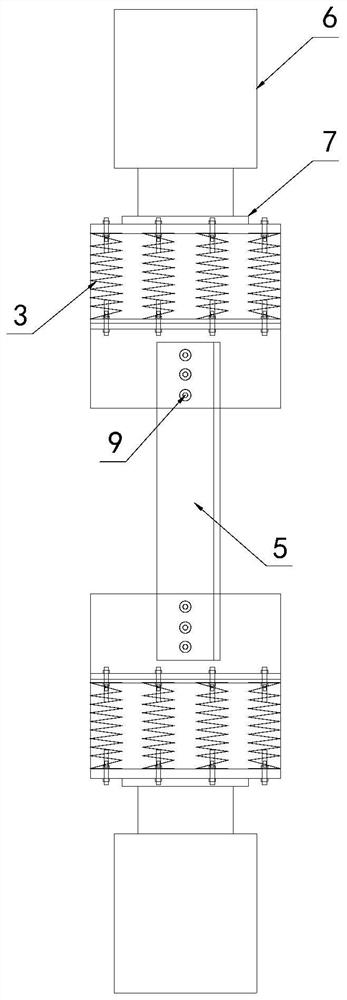
[0072] see Figure 1-Figure 2 , the present embodiment proposes a semi-rigid joint test device with adjustable stiffness, including two test assemblies arranged oppositely, a test member 5 is installed between the two test assemblies, and the two test assemblies are arranged up and down.

[0073] The upper test assembly includes a loading part 1 and a connecting part 2 , the loading part 1 is hinged to the connecting part 2 , and the loading part 1 can transfer load to the test member 5 through the connecting part 2 .

[0074] The loading part 1 includes a horizontally arranged plate one 11 and a vertically arranged plate two 12, the second plate 12 is fixedly connected to the middle position below the first plate 11, the first plate 11 and the second plate 12 form a T-shaped structure.

[0075] The connecting part 2 comprises a horizontally arranged board three 13 and a vertically arranged board four 14, the said board four 14 is fixedly connected to the middle position belo...

Embodiment 2

[0089] The difference between this embodiment and Embodiment 1 is that the constraining unit is fixedly connected to the first plate 11 and the third plate 13, specifically, one end of the spring is welded and fixed on the first plate 11, and the other One end is welded and fixed on the board three 13.


PUM


Abstract

The invention relates to the technical field of power transmission line tower tests, aims to solve the problem that an existing test device simulates hinge devices at the two ends of a test component through knife edge hinges and cannot simulate the condition that nodes at the two ends of the test component have constraints, and provides a rigidity-adjustable semi-rigid node test device. The device comprises two test assemblies which are oppositely arranged, and a test component is installed between the two test assemblies; each test assembly comprises a loading component and a connecting component, the loading component is hinged to the connecting component, and the loading component can transmit a load to the test component through the connecting component; a restraining part is arranged between the loading part and the connecting part, and the restraining rigidity of the restraining part can be adjusted; the device has the advantages that the rotation of the connecting component is limited due to the restraining effect of the restraining part, so that the deformation of the test component is restrained in reverse, the actual restraining condition of the node can be matched by adjusting the restraining rigidity of the restraining part, and the effective simulation of the semi-rigid support is realized.

Description

technical field [0001] The invention relates to the technical field of transmission line tower testing, in particular to a semi-rigid node testing device with adjustable stiffness. Background technique [0002] The structural test of transmission tower is an indispensable and important means to test and verify the overall mechanical properties and structural rationality of the tower, and to guide the optimal design of the tower structure. The existing test device uses a knife-edge hinge to simulate the hinges at both ends of the test member, and applies a load to the upper hinge support to test the performance of the test member. However, because the knife-edge hinge angle cannot be constrained, the test member will be deformed after compression Free deflection occurs, that is, there is no constraint force at the nodes at both ends of the test member, which is inconsistent with the actual stress of the tower, so the device cannot simulate the situation where the nodes at bot...

Claims


Application Information

Patent Timeline
Patent Type & Authority Applications(China)
IPC IPC(8): G01N3/02G01N3/08
CPCG01N3/02G01N3/08G01N2203/0003G01N2203/0019G01N2203/0032
Inventor 黄兴鄢秀庆马海云胡全梁明韩大刚辜良雨王劲刘翔云杨洋蒲凡冯勇李彦民李钟廖邢军周建军刘洪昌龚涛董碧霞王波何文俊刘琴叶果王伸富何江华王健钟向越杨昌金
Owner SOUTHWEST ELECTRIC POWER DESIGN INST OF CHINA POWER ENG CONSULTING GROUP CORP
Why Eureka
Try Eureka