Derived VLAN mapping technique

a mapping technique and derived vlan technology, applied in the field of computer networks, can solve the problems of inability to generally broadcast messages, inability to use hierarchical routing, and inability to improve the performance of broadcasting stations, etc., to achieve cost-effective and scaleable effects, efficient management, and cost-effective

Inactive Publication Date: 2009-08-18
CISCO TECH INC
View PDF41 Cites 31 Cited by
  • Summary
  • Abstract
  • Description
  • Claims
  • Application Information

AI Technical Summary

Benefits of technology

[0032]Advantageously, the centralized derived VLAN mapping arrangement enables efficient management in a single forwarding database that is generally more cost effective and scaleable than prior distributed solutions. The translation and forwarding structures are generally configured by software and run at line rate on the hard

Problems solved by technology

However, improper use of broadcasting can impact the performance of stations by interrupting them unnecessarily.
The IPX network number is not inherently hierarchical, so hierarchical routing is not generally available with this protocol.
The IP protocol, however, does not generally broadcast messages because its higher-level protocols maintain a history of routes to neighboring end stations.
This creates a problem for a multiprotocol switching environment that includes an IP subnet associated with a single VLAN.
This type of distributed control system is an expensiv

Method used


Image

  • Derived VLAN mapping technique
  • Derived VLAN mapping technique
  • Derived VLAN mapping technique

Examples


Embodiment Construction

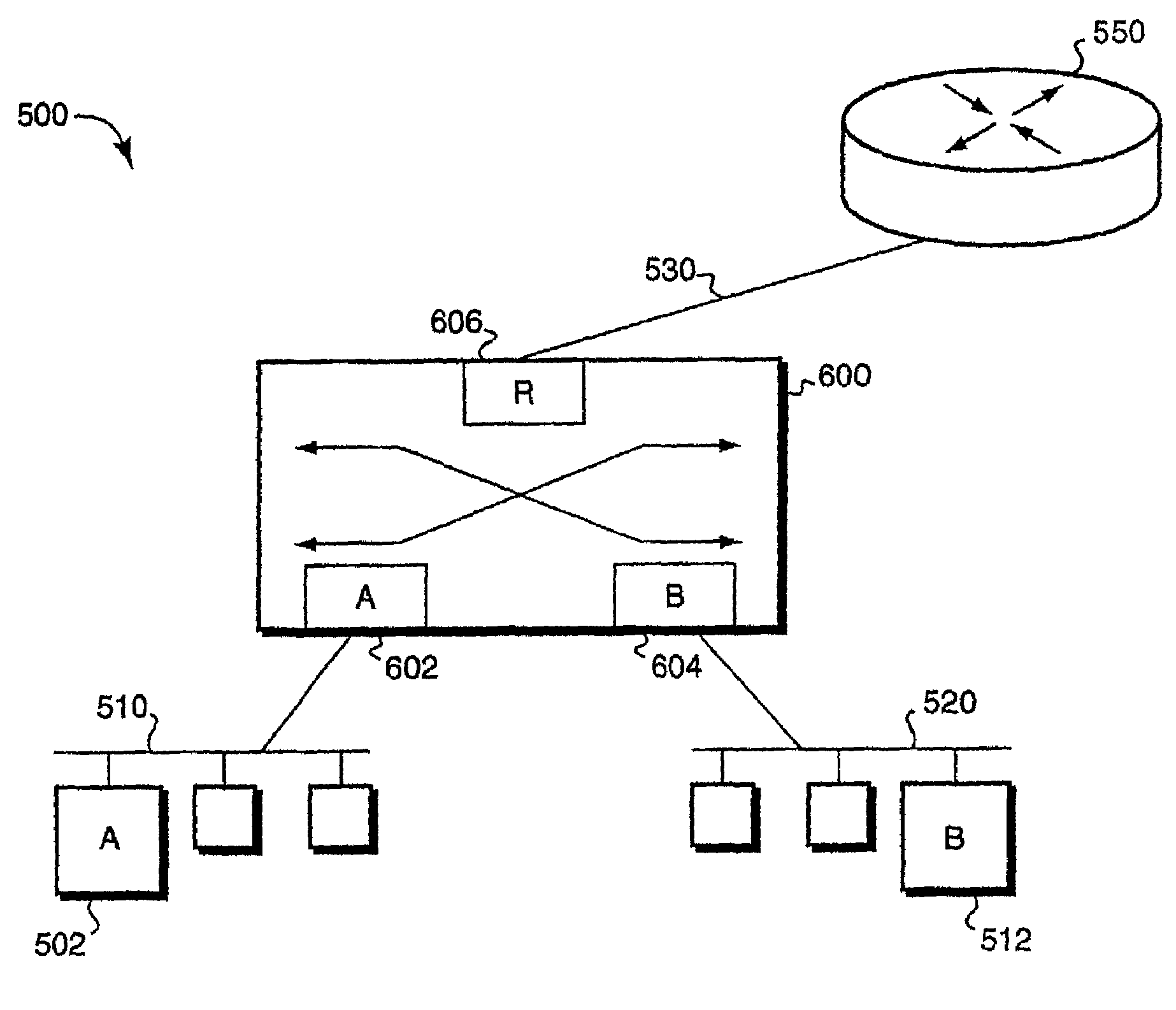
[0042]FIG. 5 is a block diagram of a computer internetwork 500 comprising a collection of interconnected communication media and subnetworks attached to a plurality of stations. The stations are typically computers comprising end stations 502, 512 and intermediate stations 550, 600. Specifically, the intermediate station 550 is a router and the intermediate station 600 is a network switch, whereas the end stations 502, 512 may include personal computers or workstations.

[0043]Each station typically comprises a plurality of interconnected elements, such as a processor, a memory and a network adapter. The memory may comprise storage locations addressable by the processor and adapter for storing software programs and data structures associated with the inventive mapping technique. The processor may comprise processing elements or logic for executing the software programs and manipulating the data structures. An operating system, portions of which are typically resident in memory and exe...


PUM


Abstract

A method of operating a switch for frames in a computer network uses one or more indicia of frame type designation found in the received frame to derive a virtual local area network (derived VLAN) value. Also, an indicia of the receiving port may be used in constructing the derived VLAN value. The switch then uses the derived VLAN value in making forwarding decisions. Broadcast domains in the computer network may then be controlled by forwarding in response to the derived VLAN value.

Description

CROSS-REFERENCE TO RELATED APPLICATIONS[0001]The present application is a continuation of commonly assigned U.S. patent application Ser. No. 09 / 038,504, now issued as U.S. Pat. No. 6,208,649, which was filed on Mar. 11, 1998, by Raymond Kloth for a Derived VLAN Mapping Technique and is hereby incorporated by reference.BACKGROUND OF THE INVENTION[0002]1. Field of the Invention[0003]This invention relates generally to computer networks and, more specifically, to a technique that enables control of broadcast domains by a switch capable of supporting different protocols within a computer internetwork.[0004]2. Background Information[0005]Communication in a computer internetwork involves the exchange of data between two or more entities interconnected by communication media. The entities are typically software programs executing on hardware computer platforms, such as end stations and intermediate stations. In particular, communication software executing on the end stations correlate and ...

Claims


Application Information

Patent Timeline
IPC IPC(8): H04L12/56H04L12/46H04L12/931
CPCH04L12/467H04L49/201H04L49/354H04L49/351
Inventor KLOTH, RAYMOND
Owner CISCO TECH INC
Why Eureka
Try Eureka