Multi-beam feed network design method based on 180 DEG directional coupler

A directional coupler and feeding network technology, applied in design optimization/simulation, specific array feeding systems, circuits, etc., can solve the problem of not being able to take into account the number of network ports and beamforming requirements at the same time, and achieve a simple network form. Effect

Active Publication Date: 2021-11-12
NORTHWESTERN POLYTECHNICAL UNIV
View PDF6 Cites 1 Cited by
  • Summary
  • Abstract
  • Description
  • Claims
  • Application Information

AI Technical Summary

Problems solved by technology

[0004] The purpose of the present invention is to provide a method for designing a multi-beam feeding network based on a 180° directional coupler to solve the technical problem that the existing multi-beam feeding network cannot simultaneously take into account the number of network ports and the beamforming requirements

Method used


Image

  • Multi-beam feed network design method based on 180 DEG directional coupler
  • Multi-beam feed network design method based on 180 DEG directional coupler
  • Multi-beam feed network design method based on 180 DEG directional coupler

Examples


Embodiment 1

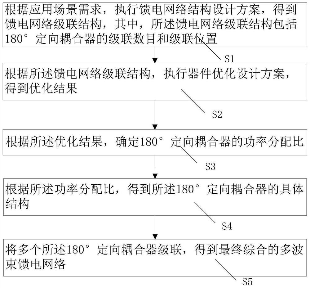
[0045] The present invention provides a method for designing a multi-beam feeding network based on a 180° directional coupler, referring to figure 1 As shown, the multi-beam feeding network design method includes:

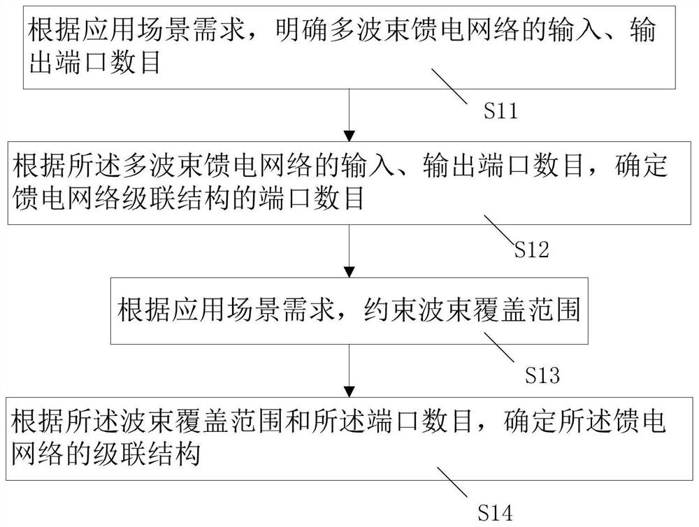
[0046] S1: According to the requirements of the application scenario, execute the feed network structure design plan to obtain the feed network cascade structure, wherein the feed network cascade structure includes the cascade number and cascade position of 180° directional couplers;

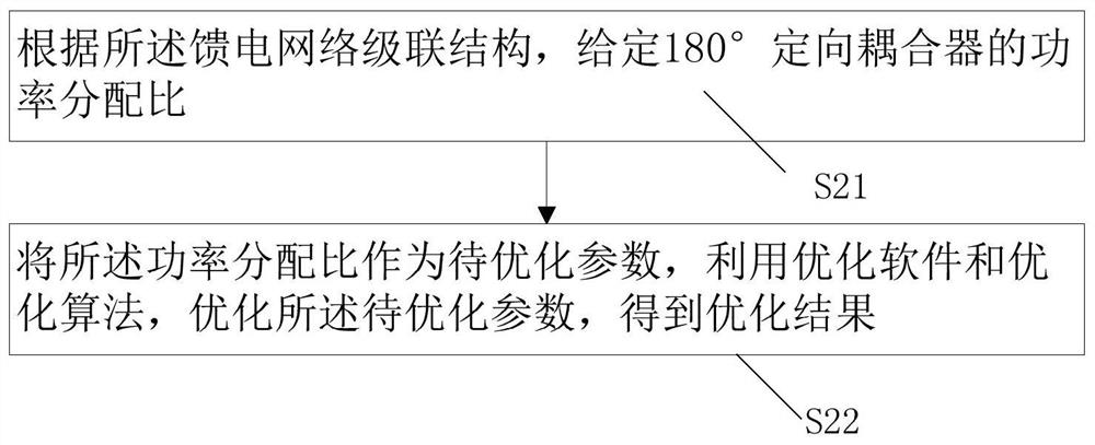
[0047] S2: According to the cascaded structure of the feed network, execute the optimization design scheme of the device, and obtain the optimization result;

[0048] S3: Determine the power distribution ratio of the 180° directional coupler according to the optimization result;

[0049] S4: Obtain the specific structure of the 180° directional coupler according to the power distribution ratio;

[0050] S5: Cascading multiple 180° directional couplers to obtain a final integrated m...

Embodiment 2

[0079] In order to further explain the design scheme, a 2×6 multi-beamforming network scheme with a flat-top pattern is taken as an example. The specific application scenario requirement is an indoor wireless communication application scenario, and the design method is described in detail.

[0080] 1. Set the number of input ports of the multi-beamforming network to 2 and the number of output ports to 6, that is, when the multi-beamforming network is connected to a 1×6 array antenna, two fixed beams can be realized;

[0081] 2. Set the target pattern as a pattern with flat top characteristics, its maximum pointing is 0°, the 3dB wave width is 32°, and the sidelobe level is <-12dB;

[0082] 3. Reference paper [L.Sun, G.X.Zhang and B.H.Sun, "Method of Synthesizing Orthogonal Beam-Forming Networks Using QR Decomposition", IEEE Access, vol.7, pp.325-331, 2018.], any 180° orientation The coupler can be expressed as a mathematical model of the Givens matrix in the real number field....


PUM


Abstract

The invention discloses a multi-beam feed network design method based on a 180 DEG directional coupler. The method comprises the following steps: S1, executing a feed network structure design scheme according to the demands of an application scene, and obtaining a feed network cascade structure; S2, executing a device optimization design scheme according to the feed network cascade structure to obtain an optimization result; S3, determining the power distribution ratio of the 180 DEG directional coupler according to the optimization result; S4, obtaining a specific structure of the 180 DEG directional coupler according to the power distribution ratio; and S5, cascading the plurality of 180 DEG directional couplers to obtain a final comprehensive multi-beam feed network. The multi-beam feed network design method based on the 180 DEG directional coupler can solve the technical problem that an existing multi-beam feed network cannot give consideration to the number of network ports and the beamforming requirement at the same time.

Description

technical field [0001] The invention relates to the technical field of network design, in particular to a method for designing a multi-beam feeding network based on a 180° directional coupler. Background technique [0002] In the evolution of mobile communication, in order to optimize and improve the coverage of wireless electromagnetic waves, the beamforming network based on multi-antenna system has become one of the most important key technologies in 4G / 5G mobile communication base stations. Traditional pure digital beamforming requires each antenna to be configured with a dedicated RF chain (RF chain), but in the massive MIMO system of 5G, the number of antennas increases exponentially, and it is no longer affordable to configure a corresponding RF chain for each antenna. RF link overhead. To reduce hardware expenses, hybrid beamforming networks emerged. The hybrid beamforming network adopts a hybrid architecture combining digital and analog, which can effectively reduc...

Claims


Application Information

Patent Timeline
Patent Type & Authority Applications(China)
IPC IPC(8): H01Q21/00H01Q21/06H04B7/0426H04B7/06G06F30/18G06F30/20
CPCH01Q21/0006H01Q21/06H04B7/0426H04B7/0617G06F30/18G06F30/20Y02D30/70
Inventor 孙莉周世钢张关喜郭梓
Owner NORTHWESTERN POLYTECHNICAL UNIV
Why Eureka
Try Eureka