
Novel friction pendulum support

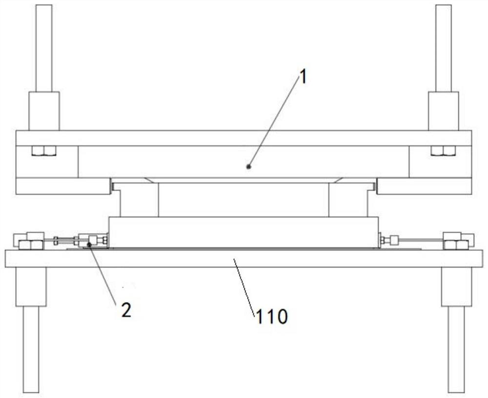
A friction pendulum bearing, a new type of technology, applied in the field of bridge shock absorption, can solve the problems of affecting the force system of the bridge, leakage of filling materials, large structural size, etc., achieve high reliability, good economy and durability, and avoid lifting Effect

Pending Publication Date: 2021-11-16
CHENGDU XINTU TECH +1
View PDF1 Cites 0 Cited by
  • Summary
  • Abstract
  • Description
  • Claims
  • Application Information

AI Technical Summary

Problems solved by technology

[0003] The mainstream friction pendulum bearing is the structure described in JT / T927-2014 "Hyperboloid Spherical Isolation Bearing for Bridges". It has a simple structure and good manufacturability, and is widely used in highway bridges. Under working conditions, the height of the support will change, which will affect the stress system of the bridge; in this regard, a combined structure of speed locker + friction pendulum support is proposed (see patent CN201891073U for a friction pendulum lock support), by adding The planar sliding pair adapted to normal temperature displacement solves the problem of the height change of the support, and at the same time, it can identify earthquakes more accurately, but because the velocity locker needs to bear a large horizontal locking force (the design fusing force of the shear pin of the support), its The structure size is large, the economy is very poor, and the speed locker will have the problem of filling leakage when it is in service for a long time, and the durability needs to be improved

Method used


Image

  • Novel friction pendulum support
  • Novel friction pendulum support
  • Novel friction pendulum support

Examples


Embodiment Construction

[0054] In the present invention, unless otherwise clearly specified and limited, terms such as "installation", "connection", "connection" and "fixation" should be understood in a broad sense, for example, it can be a fixed connection or a detachable connection , or integrated; it can be directly connected or indirectly connected through an intermediary, it can be the internal communication of two elements or the interaction relationship between two elements. The "first", "second" and similar words mentioned in this application do not indicate any order, quantity or importance, but are only used to distinguish different components. Likewise, words like "a" or "one" do not denote a limitation in number, but indicate that there is at least one. In the implementation of this application, "and / or" describes the association relationship of associated objects, indicating that there may be three types of relationships, for example, A and / or B, which may mean: A exists alone, A and B e...


PUM


Abstract

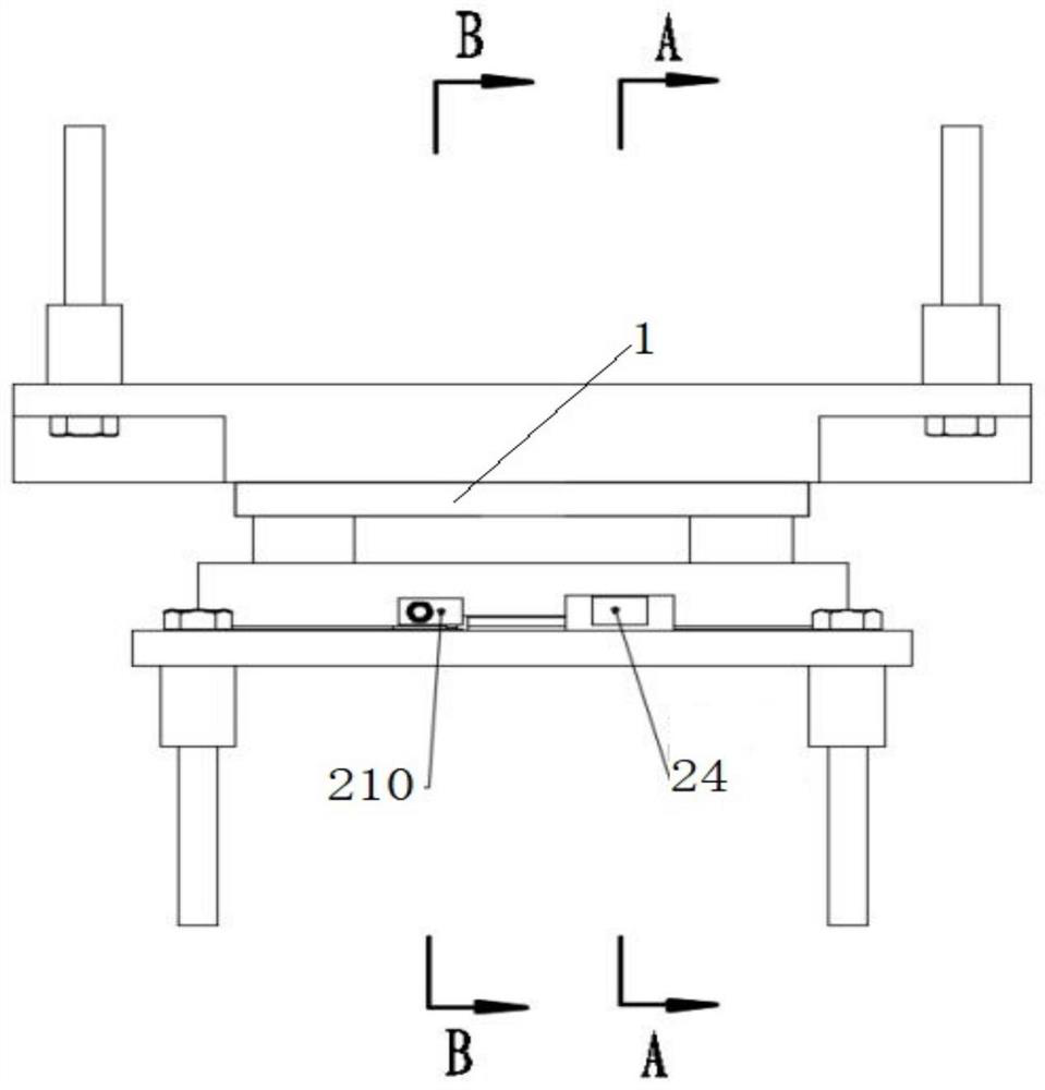
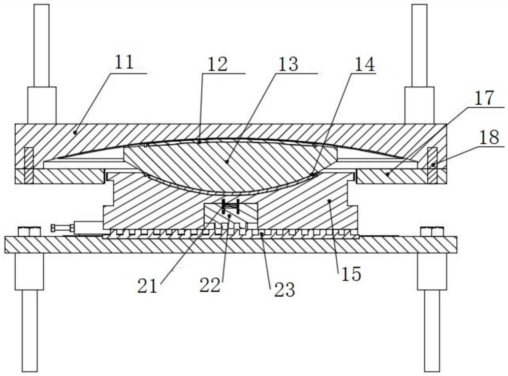
The invention relates to the technical field of bridge engineering, and particularly discloses a novel friction pendulum support which comprises a bottom plate, a locking mechanism, a reset device and a support assembly. The locking mechanism comprises an elastic clamping tooth part, a rack plate used in cooperation with the elastic clamping tooth part and a trigger locking device. The support assembly comprises a first curved surface sliding pair, a second curved surface sliding pair, a third plane sliding pair and an anti-shearing assembly used for restraining the first curved surface sliding pair. Under a normal working condition, the anti-shearing assembly restrains the first curved surface sliding pair. Under the earthquake working condition, the trigger locking device is locked, the rack plate and the elastic clamping tooth part interact to enable a third plane sliding pair to be restrained, meanwhile, the anti-shearing assembly is sheared off, and the first curved surface sliding pair is released. After the earthquake is finished, the reset device drives the elastic clamping tooth part to move towards one side close to the support assembly, the locking device is triggered to recover to the initial state, and reset is completed. Compared with a traditional speed locking type friction pendulum support, the novel friction pendulum support is better in economical efficiency and durability, and resetting can be effectively achieved.

Description

technical field [0001] The invention relates to the technical field of bridge damping, and more specifically relates to a novel friction pendulum support. Background technique [0002] The application of shock absorption and isolation technology in the field of bridge construction is mainly to use shock absorption and isolation devices to improve safety and reduce structural damage when encountering earthquakes. Friction pendulum anti-seismic isolation bearing is the mainstream anti-vibration isolation device at the present stage. Its structural principle is to meet the normal functional requirements of the bridge and at the same time adopt the mutual sliding between the friction pendulum surfaces similar to the pendulum principle to delay the structural period to achieve the anti-vibration effect. , and at the same time, the frictional energy consumption between the pendulum surfaces achieves the effect of shock absorption. [0003] The mainstream friction pendulum bearing...

Claims


Application Information

Patent Timeline
Patent Type & Authority Applications(China)
IPC IPC(8): E01D19/04
CPCE01D19/048
Inventor 张启帆刘成刘海亮邱廷琦任杰骆明成陈宏王海桥兰鹏周孝林杨蕊矫
Owner CHENGDU XINTU TECH
Learn More