An anti-cross-cavity structure between parallel flow channels

A cavity structure, anti-string technology, applied in the field of the cooling plate structure of the combustion chamber, can solve the problems of affecting the performance, reducing the cooling effect of the combustion chamber, and small brazing area, so as to increase the brazing area, improve the cooling performance, and avoid the medium The effect of the string cavity

Active Publication Date: 2022-06-07
XIAN YUANHANG VACUUM BRAZING TECH
View PDF6 Cites 0 Cited by
  • Summary
  • Abstract
  • Description
  • Claims
  • Application Information

AI Technical Summary

Problems solved by technology

[0003] However, during use, due to the small brazing area between the cavity rib 15 and the flange 11, it is easy to cause the cooling medium between the adjacent cavities 14 to cross the cavity, reduce the cooling effect of the combustion chamber, and affect the performance

Method used


Image

  • An anti-cross-cavity structure between parallel flow channels
  • An anti-cross-cavity structure between parallel flow channels
  • An anti-cross-cavity structure between parallel flow channels

Examples


Embodiment Construction

[0026] The present invention will be described in detail below with reference to the accompanying drawings and specific embodiments.

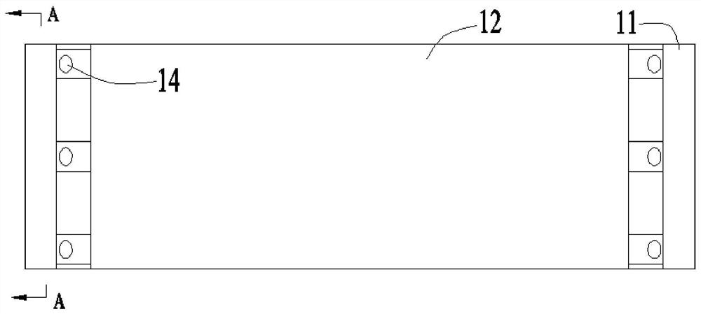
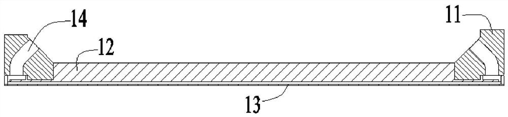
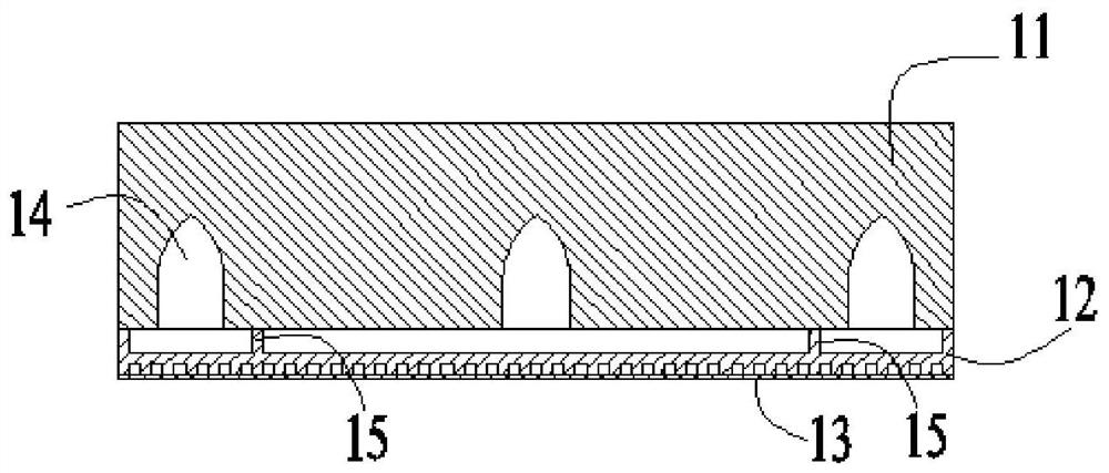
[0027] The invention discloses an anti-cross-cavity structure between parallel flow channels, such as Figure 4 As shown, it includes a base plate 12, the top surface of the base plate 12 is connected with a flange 11, and the bottom surface of the base plate 12 is connected with a cover plate 13; there are several cavities 14 between the flange 11 and the top surface of the base plate 12; the bottom of the flange 11 A number of strip-shaped grooves are opened; the top surface of the base plate 12 is extended with a number of second compartment plates 152, the second compartment plates 152 and the strip-shaped grooves of the flange 11 have the same number and corresponding positions, and the second compartment plate 152 The height of the cavity plate 152 is greater than the first distance, and the first distance is the distance between the bott...


PUM


Abstract

The invention discloses an anti-cavity structure between parallel flow channels, which includes a base plate, the top surface of the base plate is connected with a flange, and the bottom surface of the base plate is connected with a cover plate; there are several cavities between the flange and the top surface of the base plate; The bottom of the flange is provided with several strip-shaped grooves; the top surface of the substrate is extended upwards with several second compartment plates, the number of the second compartment plates is equal to the strip-shaped slots of the flange, and the positions correspond; The top plate of the base plate is extended upwards to set the second compartment plate, and a strip-shaped groove is opened on the bottom surface of the flange. When installing, the top of the second compartment plate can be inserted into the strip-shaped groove and passed through the top of the second compartment plate. Brazing with the contact surface of the strip groove greatly increases the brazing area between the two cavities compared with the brazing area between the top surface of the original compartment rib and the flange, avoiding the need for adjacent cavities The medium string cavity between the bodies improves the cooling performance of the combustion chamber.

Description

technical field [0001] The invention belongs to the technical field of cooling plate structures of combustion chambers, and in particular relates to an anti-cross-cavity structure between parallel flow channels. Background technique [0002] Combustion chamber is an important part of aero-engine. Due to its very high temperature, various cooling methods are required to achieve cooling and cooling of the combustion chamber wall. like figure 1 , figure 2 and image 3 As shown, it is a conventional design structure of an existing cooling plate. In the cooling plate, the flange 11 , the base plate 12 and the cover plate 13 are sequentially arranged from top to bottom, and brazing is respectively performed between the flange 11 and the base plate 12 and between the base plate 12 and the cover plate 13 . There are parallel three-way cavities 14 in the flange 11 , and adjacent cavities 14 are separated by cavity ribs 15 to ensure that each cavity 14 is independent. [0003] H...

Claims


Application Information

Patent Timeline
Patent Type & Authority Patents(China)
IPC IPC(8): F23R3/60F23R3/42
CPCF23R3/60F23R3/42F23R2900/03043Y02T10/12
Inventor 李文昌李淑芳刘紫玉任航航琚明
Owner XIAN YUANHANG VACUUM BRAZING TECH
Why Eureka
Try Eureka