
Manufacturing method of coiled pipe heat exchanger core

A manufacturing method and serpentine tube technology, applied in the direction of manufacturing tools, metal processing equipment, welding equipment, etc., can solve the problems of easy deformation of the partition, high difficulty of assembly, and increased difficulty of assembly, so as to control the deformation of the partition and reduce the assembly cost. effect of difficulty

Inactive Publication Date: 2021-09-21
XIAN YUANHANG VACUUM BRAZING TECH
View PDF6 Cites 0 Cited by
  • Summary
  • Abstract
  • Description
  • Claims
  • Application Information

AI Technical Summary

Problems solved by technology

Since there are 2400 serpentine tubes in the core of the heat exchanger, the diameter of the serpentine tubes is 2.2mm, and the fitting gap between the serpentine tubes and the upper plate, lower plate, and partition is very small, and the overall assembly is extremely difficult; The thickness is only 1mm, and the partitions are easily deformed when high-temperature gas passes through the channels between the partitions, which undoubtedly increases the difficulty of assembly

Method used


Image

  • Manufacturing method of coiled pipe heat exchanger core
  • Manufacturing method of coiled pipe heat exchanger core
  • Manufacturing method of coiled pipe heat exchanger core

Examples


Embodiment Construction

[0039] The present invention will be described in further detail below in conjunction with the accompanying drawings, which are explanations rather than limitations of the present invention.

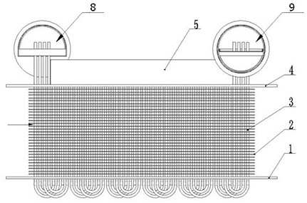
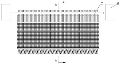
[0040] see Figure 4~Figure 6 , a method for manufacturing a serpentine tube heat exchanger core, comprising the following steps:

[0041] (1) Separately process serpentine tube 3, lower plate 1, upper plate 4, cover plate 5, oil collecting plate 7 and multiple partitions 2, lower plate 1, upper plate 4, partition 2, and upper oil collecting plate 7 Both are provided with through holes matching the outer diameter of the serpentine tube 2; lap joints 6 are processed on the upper plate 4 and the cover plate 5, so that the upper plate 4 and the cover plate 5 can be overlapped and assembled;

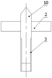
[0042] (2) After cleaning the upper plate 4, cover plate 5, partition plate 2, oil collecting plate 7 and lower plate 1, insert an assembly tool 10 with a guide cone into the upper opening of each ser...


PUM

PropertyMeasurementUnit
Diameteraaaaaaaaaa
Brushing thicknessaaaaaaaaaa

Abstract

The invention discloses a manufacturing method of a coiled pipe heat exchanger core. The manufacturing method comprises the following steps that coiled pipes, an upper plate, a cover plate, an oil collecting plate and a plurality of partition plates are machined respectively, and lap joints are machined on the upper plate and the cover plate; an assembly tool with a guide cone is inserted into an opening in the upper end of each coiled pipe, a lower plate and the plurality of partition plates penetrate through the guide cones to be assembled on the coiled pipes under the guidance of the assembly tools, and the positions between the lower plate and the partition plates are positioned through positioning tools; the to-be-brazed positions of the coiled pipes and the upper plate are coated with brazing filler metal; the cover plate is assembled on the upper plate, the oil collecting plate and connectors are welded into an oil collecting plate assembly, and the oil collecting plate assembly is assembled on the coiled pipes through the assembly tools; the to-be-brazed positions of the coiled pipes and the oil collecting plate assembly are coated with brazing filler metal; and brazing tools are additionally arranged on the periphery of a heat exchanger core body assembly, and the heat exchanger core body is placed in a vacuum brazing furnace to be subjected to vacuum brazing. According to the manufacturing method, by designing the assembly tools, the positioning tools and the brazing tools, the manufacturing difficulty is overcome, and the machining difficulty is reduced.

Description

technical field [0001] The invention belongs to the technical field of aerospace precision manufacturing, and relates to a method for manufacturing a serpentine tube heat exchanger core. Background technique [0002] The schematic diagram of the core body of the engine serpentine heat exchanger is as follows: figure 1 , figure 2 and image 3 As shown, the engine serpentine heat exchanger core is composed of a lower plate, a partition, a serpentine tube, an upper plate, a cover plate, a joint, and an oil collecting plate. The material of the engine serpentine heat exchanger core is Austenitic Body stainless steel. Vacuum brazing and argon arc welding are used to form chambers A and B between the parts, and the medium circulates in the chambers A and B to cool the high-temperature gas entering between the partitions. Since there are 2400 serpentine tubes in the core of the heat exchanger, the diameter of the serpentine tubes is 2.2mm, and the fitting gap between the serpe...

Claims


Application Information

Patent Timeline
IPC IPC(8): B23P15/26B23K1/008
CPCB23P15/26B23K1/008
Inventor 康路路李同心兰新杰任军董文军李俊峰
Owner XIAN YUANHANG VACUUM BRAZING TECH
Learn More