A steam turbine diaphragm assembly process

An assembly process and steam turbine technology, applied in metal processing, manufacturing tools, metal processing equipment, etc., can solve the problems of unstable molding quality, numerous assembly processes, and low manufacturing efficiency, so as to improve the assembly molding quality and reduce the difficulty of assembly technology , The effect of reducing manufacturing costs

Active Publication Date: 2020-03-20
DONGFANG TURBINE CO LTD
View PDF8 Cites 0 Cited by
  • Summary
  • Abstract
  • Description
  • Claims
  • Application Information

AI Technical Summary

Problems solved by technology

From this assembly process, it can be clearly seen that the assembly process of the existing steam turbine diaphragm not only needs to open a welding groove on the assembly surface of each guide vane, but also has many assembly processes. These technical measures will directly lead to a significant increase in the assembly cycle of the steam turbine diaphragm. lengthening, manufacturing inefficiencies, and substantially increasing the manufacturing cost of steam turbine diaphragms
In addition, the existing steam turbine diaphragm assembly process has a welding process for the cascade composed of multiple guide vanes. The welding process of the cascade is likely to cause a large deformation of the entire cascade due to welding, so that the assembly size of the cascade It is difficult to guarantee, which will directly affect the assembly accuracy and molding quality of the partition
[0005] To sum up, the existing assembly process of steam turbine diaphragm has technical problems such as long cycle, low efficiency, high cost, unstable molding quality, etc.

Method used


Image

  • A steam turbine diaphragm assembly process
  • A steam turbine diaphragm assembly process
  • A steam turbine diaphragm assembly process

Examples


Embodiment 1

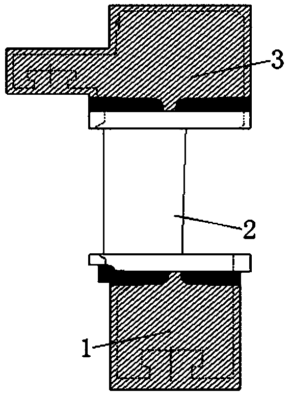
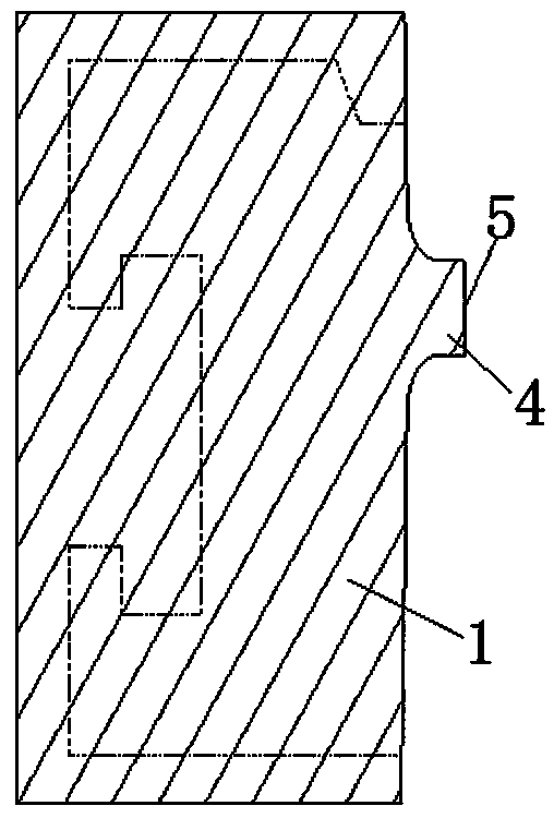
[0024] The present invention relates to an assembly process of a steam turbine baffle, wherein the steam turbine baffle is mainly composed of a baffle body, a plurality of guide blades and a baffle outer ring, and the outer periphery of the baffle body has a raised positioning notch (see image 3 As shown, 1 is the partition body, 4 is the positioning spigot, and 5 is the datum plane), each guide vane is mainly composed of an inner edge plate, a blade body and an outer edge plate; the assembly process includes the following technical measures:

[0025] - Process the assembly surface of the edge plate of each guide vane to be smooth, without welding groove structure;

[0026] -Fit the inner edge plates of each guide vane on the outer periphery of the partition body in turn, specifically, take the top surface of the positioning notch raised on the periphery of the partition body as a reference—that is, the reference plane for brushing, and place the inner edge of each guide vane ...

Embodiment 2

[0030] The present invention relates to an assembly process of a steam turbine baffle, wherein the steam turbine baffle is mainly composed of a baffle body, a plurality of guide blades and a baffle outer ring, and the outer periphery of the baffle body has a raised positioning notch (see image 3 As shown, 1 is the partition body, 4 is the positioning spigot, and 5 is the datum plane), each guide vane is mainly composed of an inner edge plate, a blade body and an outer edge plate; the assembly process includes the following technical measures:

[0031] - Process the assembly surface of the edge plate of each guide vane to be smooth, without welding groove structure;

[0032] -Fit the inner edge plates of each guide vane on the outer periphery of the partition body in turn, specifically, take the top surface of the positioning notch raised on the periphery of the partition body as a reference—that is, the reference plane for brushing, and place the inner edge of each guide vane ...

Embodiment 3

[0036] The present invention relates to an assembly process of a steam turbine baffle, wherein the steam turbine baffle is mainly composed of a baffle body, a plurality of guide blades and a baffle outer ring, and the outer periphery of the baffle body has a raised positioning notch (see image 3 As shown, 1 is the partition body, 4 is the positioning spigot, and 5 is the datum plane), each guide vane is mainly composed of an inner edge plate, a blade body and an outer edge plate; the assembly process includes the following technical measures:

[0037] - Process the assembly surface of the edge plate of each guide vane to be smooth, without welding groove structure;

[0038] -Fit the inner edge plates of each guide vane on the outer periphery of the partition body in turn, specifically, take the top surface of the positioning notch raised on the periphery of the partition body as a reference—that is, the reference plane for brushing, and place the inner edge of each guide vane ...


PUM

PropertyMeasurementUnit
interferenceaaaaaaaaaa

Abstract

The invention discloses an assembly process of a steam turbine diaphragm. The steam turbine diaphragm is mainly composed of a diaphragm body, a plurality of guide blades and an outer ring of the diaphragm. The guide vane is mainly composed of an inner edge plate, a blade body and an outer edge plate Composition; the clapboard assembly process includes the following technical measures: - processing the edge plate assembly surface of each guide vane flat, without welding groove structure; - brushing the inner edge plates of each guide vane on the outer periphery of the clapboard body in turn , so that each guide vane forms a cascade on the outer periphery of the partition body, and the partition body and the cascade form a mating assembly; -Match the outer ring of the diaphragm and the mating assembly; The outer ring of the plate is assembled on the mating assembly in a red-fitting manner, and the outer ring of the clapboard is located at the outer edge plate of the cascade of the mating assembly to obtain a steam turbine diaphragm. The assembling technique of the invention is less difficult, and has the characteristics of short assembling period, high assembling efficiency, low manufacturing cost, high assembling precision and the like.

Description

technical field [0001] The invention relates to a forming technology of a steam turbine partition, in particular to an assembly process of a steam turbine partition. Background technique [0002] The steam turbine diaphragm is the partition wall of the various stages in the steam turbine. It is mainly composed of a diaphragm body, a plurality of guide vanes (ie, stationary vanes) and the outer ring of the diaphragm. The two ends of the blade body of the guide vane have inner and outer edge plates. , that is, the guide vane is a self-contained crown structure. [0003] The assembly of the steam turbine diaphragm is to combine the diaphragm body, multiple guide vanes and the outer ring of the diaphragm to form a whole. [0004] see figure 1 and figure 2 As shown, the assembly process of the existing steam turbine diaphragm is to process a welded groove structure on the edge plate assembly surface of each guide vane 2 first, and the welded groove structure is at the matchin...

Claims


Application Information

Patent Timeline
Patent Type & Authority Patents(China)
IPC IPC(8): B23P11/02B23P19/02
CPCB23P11/025B23P19/02
Inventor 蒋超静黄斌王斌彭刚裴金廷欧定明余萍王俊宝张从平谭显云李含俊林治美唐绍军赵鹏飞王大勇王喆
Owner DONGFANG TURBINE CO LTD
Why Eureka
Try Eureka