A sliding floating caliper braking mechanism

A technology of brake mechanism and floating caliper, which is applied in the direction of brake actuators, brake types, brake components, etc., can solve problems such as insufficient supply pressure, potential safety hazards of gas storage tanks, and brake failure, so as to avoid the decline of braking force , Avoid potential safety hazards and prolong service life

Active Publication Date: 2019-02-26
HAIAN COUNTY SHENLING ELECTRICAL APPLIANCE MFG
View PDF7 Cites 0 Cited by
  • Summary
  • Abstract
  • Description
  • Claims
  • Application Information

AI Technical Summary

Problems solved by technology

[0005] In order to overcome the braking effect of most products in the prior art in the form of pneumatic or hydraulic braking, there are the following problems when using pneumatic braking or hydraulic braking: ① When the elevator is in use, the space in the elevator shaft is narrow and it is impossible to install a high-power air compressor Machine, the cost of using a small-power air compressor is relatively high and will generate noise, and the cost of laying pipelines when using a large air compressor to supply air to the brake is high, the interface is prone to aging and leakage, the floor area is large, and the maintenance cost is high. There are certain security risks
③ Both hydraulic pressure and air pressure have one thing in common, that is, they need to use a large number of pipelines for laying. If the pipeline laying distance is too long, it will easily lead to insufficient supply pressure of hydraulic pressure or air pressure, which will lead to braking failure or poor braking effect. It is easy to burst the pipe phenomenon, which also leads to the failure of the brake.

Method used


Image

  • A sliding floating caliper braking mechanism
  • A sliding floating caliper braking mechanism
  • A sliding floating caliper braking mechanism

Examples


Embodiment Construction

[0027] The present invention will be described in further detail below in conjunction with the accompanying drawings and embodiments. It should be understood that the specific embodiments described here are only used to explain the present invention, not to limit the present invention.

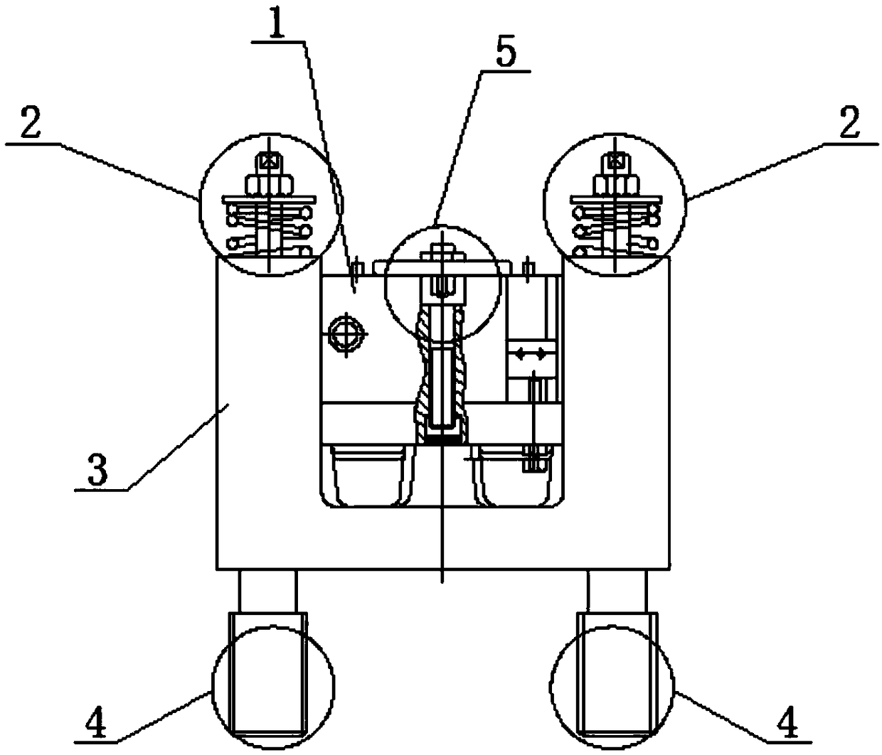
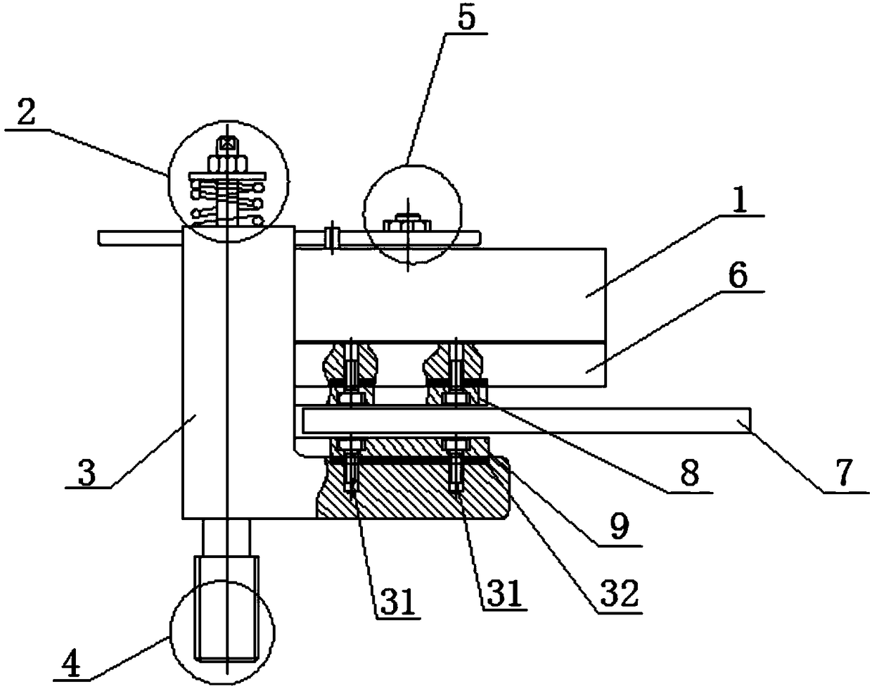
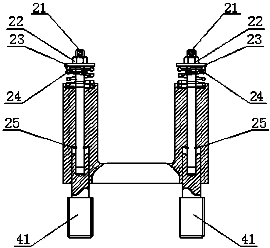
[0028] The invention discloses a sliding floating caliper braking mechanism, such as figure 1 As shown: the main body is a caliper bracket 3, the caliper bracket 3 is L-shaped as a whole, and the caliper bracket 3 includes a brake caliper body 1, a brake disc 7, a spring limiting device 2 and an independent adjustment device for friction plates 5. The four are all arranged in the L-shaped caliper bracket 3; the side of the L-shaped caliper bracket 3 perpendicular to the ground is provided with a recessed area, forming two raised areas; the brake caliper body 1, the brake disc 7 There is an up-down relationship and the two do not touch when they are still, such as figure 2 As shown: the fric...


PUM


Abstract

A sliding floating caliper braking mechanism. The main body of the mechanism is a caliper body support frame (3), which is L-shaped as a whole. The caliper body support frame (3) comprises a brake caliper body (1), a brake disc (7), a spring stop device (2), and a friction plate independent adjustment device (5); the four components are all disposed in the L-shaped caliper body support frame (3). One side, perpendicular to the ground, of the L-shaped caliper body support frame (3) is provided with a recessed area, so that two raised areas are formed. The brake caliper body (1) is above the brake disc (7) in a vertical direction, and the brake caliper body (1) and the brake disc (7) are not in contact with each other when being static. The friction plate independent adjustment device (5) is disposed on the brake caliper body (1) in the vertical direction.

Description

technical field [0001] The invention relates to the technical field of disc brakes, in particular to a sliding floating caliper braking mechanism. Background technique [0002] In daily life, elevators are more and more recognized and used by people due to their fast and efficient advantages. Therefore, elevators are used as the main means of transportation in major shopping malls and residential quarters. With the continuous application of elevators, various accidents such as elevator brake failures occur frequently, which not only cause personal injury, but even life-threatening in severe cases. Maintenance takes a long time, and it is easy to cause congestion in shopping malls, hospitals and other places with a relatively large flow of people. Therefore, most of the time, the maintenance frequency of elevator brakes is relatively low, resulting in poor contact or adhesion of the contacts caused by the use of the brakes beyond the use time limit. Contact effect Unsatisfac...

Claims


Application Information

Patent Timeline
Patent Type & Authority Patents(China)
IPC IPC(8): F16D65/092F16D65/14F16D121/14
CPCF16D65/092F16D65/14F16D2121/14
Inventor 范小斌李申顾建国杨俊毛剑
Owner HAIAN COUNTY SHENLING ELECTRICAL APPLIANCE MFG
Why Eureka
Try Eureka