Curved glass flatness detection device with windscreen wiper detection mechanism
A detection device and curved glass technology, which is applied in the direction of electromagnetic measuring device, electric/magnetic roughness/irregularity measurement, etc., can solve the problems affecting the accuracy of detection and judgment error, so as to increase accuracy and ensure accuracy , Increase the effect of performance
- Summary
- Abstract
- Description
- Claims
- Application Information
AI Technical Summary
Problems solved by technology
Method used
Image
Examples
Embodiment 1
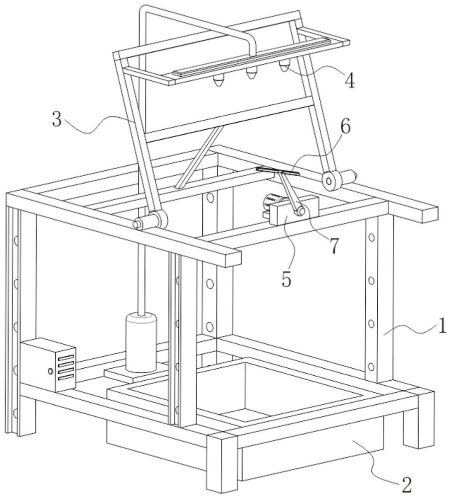
[0023] The present invention provides a technical solution: it is suitable for a curved glass flatness detection device with a wiper detection mechanism, please refer to figure 1 , including mounting frame 1 and collection box 2;
[0024] see figure 1 , the collection box 2 is installed at the bottom of the inner cavity of the mounting frame 1, and the upper part of the collection box 2 is open to collect the water generated during the detection and cleaning process. Above the mounting frame 1, leaning against the front side of the bracket 3 and at the rear side of the detection device 6, a water spray device 4 is installed on the outer wall of the front side of the bracket 3, and the water spray device 4 is composed of a water tank, a water pump, a connecting pipe and a spray head. The water pump transports the water inside the water tank to the spray head, the spray head sprays the water on the curved glass, and then the drive motor works to make the wiper body 7 work to sw...
Embodiment 2
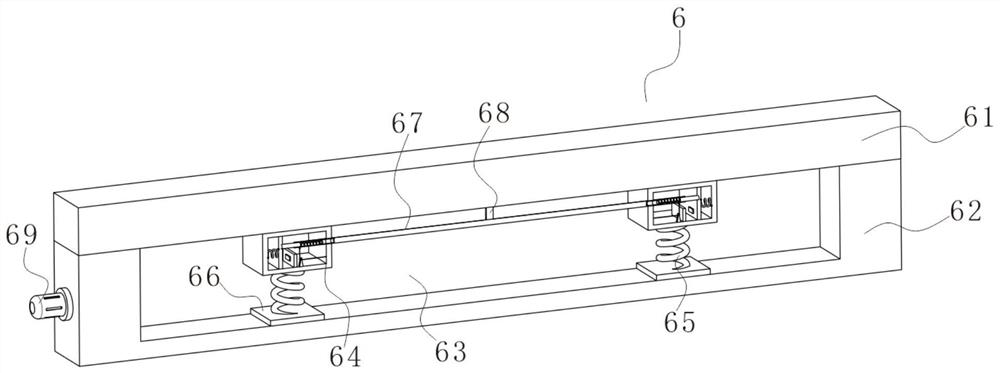
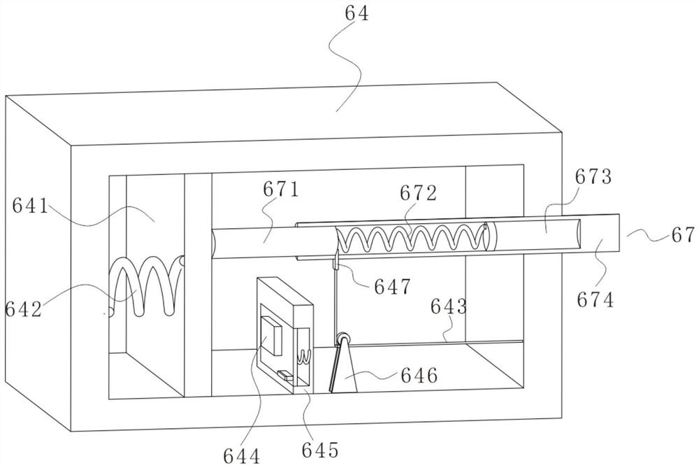
[0028] see figure 2 and image 3 On the basis of Embodiment 1, the connecting rope 67 includes a rope body, and the left and right ends of the rope body are fixedly installed with connecting rods 674. The outer wall of one side of the connecting rod 674 close to the support block 64 is provided with a mounting hole 673. The mounting hole 673 A connecting rod 671 is slidably installed in the inner cavity, a contraction spring 672 is fixedly installed between the connecting rod 671 and the inner cavity of the installation hole 673 , and one end of the connecting rod 671 away from the connecting rod 674 is fixedly connected to the outer wall of the side of the moving plate 641 away from the return spring 642 , the front side of the inner cavity of the mounting hole 673 is slidably inserted with a limit block 647, the limit block 647 is located on the inner side of the connecting rod 671, a pull rope 643 is fixedly installed between the front side of the limit block 647 and the i...
Embodiment 3
[0031] see Figure 5 and Image 6 , On the basis of Embodiment 1, the inner cavity of the scraper 61 is provided with a groove 611, the interior of the groove 611 is filled with air, a connecting spring 612 is evenly arranged between the inner cavities of the groove 611, and the front side of the inner cavity of the installation groove 63 is fixed An installation sleeve 625 is installed. The rear side of the inner cavity of the installation sleeve 625 is communicated with the inner cavity of the groove 611 through the connecting pipe 626. The inner cavity of the front side wall of the installation plate 62 is provided with a receiving groove. The receiving groove is connected, and the left and right sides of the receiving groove are slidably inserted with moving rods 621. When the scraper 61 is in contact with the curved glass bulge and the scraper 61 is dented, the groove 611 will be squeezed , the air inside the groove 611 will be squeezed into the installation sleeve 625 t...
PUM
 Abstract
Description
Claims
Application Information
 - R&D
- Intellectual Property
- Life Sciences
- Materials
- Tech Scout
- Unparalleled Data Quality
- Higher Quality Content
- 60% Fewer Hallucinations
Browse by: Latest US Patents, China's latest patents, Technical Efficacy Thesaurus, Application Domain, Technology Topic, Popular Technical Reports.
© 2025 PatSnap. All rights reserved.Legal|Privacy policy|Modern Slavery Act Transparency Statement|Sitemap|About US| Contact US: help@patsnap.com


