Rail surface standard line rapid marking device
A standard line and rail surface technology, which is applied to measuring devices, jetting devices, instruments, etc., can solve the problems of inability to complete the standard line marking task of catenary pillar rail surface on time, low operation efficiency, and low degree of automation, and achieves a high level of improvement. The effect of working efficiency, reducing workload and reducing labor intensity
- Summary
- Abstract
- Description
- Claims
- Application Information
AI Technical Summary
Problems solved by technology
Method used
Image

Examples
Embodiment 1
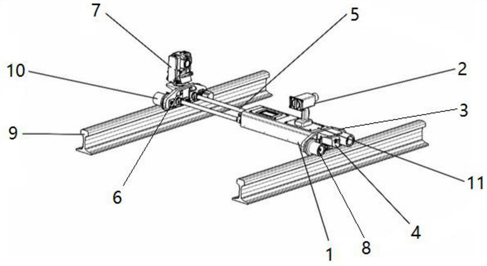
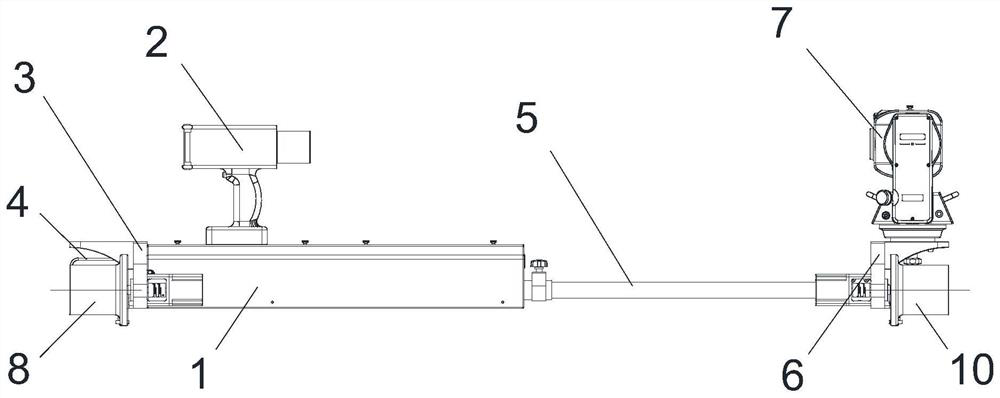
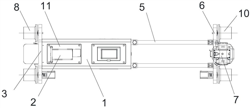
[0045] The embodiment of the present invention provides a rail surface standard line rapid marking device, such as Figure 1-Figure 9 As shown, it includes: an outer shell 1, a marking gun 2 is arranged on the upper surface of the outer shell 1, and a first side plate 3 is arranged on one side of the outer shell 1, and the first side plate 3 is far away from the outer shell 1- The first guide wheel assembly and the side limit measuring device 4 are arranged on the side, the telescopic assembly 5 is arranged on the side of the outer casing 1 away from the first side plate 3, and the second telescopic assembly 5 is arranged on the side far away from the outer casing 1. The side plate 6 is provided with a second guide wheel assembly on the side away from the outer casing 1 , and a top limit measuring device 7 is provided on the upper surface of the second side plate 6 .
[0046] The working principle and beneficial effects of the above-mentioned technical solution are as follows:...
Embodiment 2
[0048] On the basis of above-mentioned embodiment 1, as Figure 1-Figure 4 As shown, the first guide wheel assembly includes a first guide wheel 8, the first guide wheel 8 is rotatably connected to the side wall of the first side plate 3, and the first guide wheel 8 is connected to the side rail 9. Adaptation, the first guide wheel 8 can move along the upper surface of the track 9, the first guide wheel 8 is set to two, at least one of the two first guide wheels 8 has a first drive motor, The first drive motor is used to drive the first guide wheels 8, and the side limit measuring device 4 is arranged between the two first guide wheels 8;
[0049] The second guide wheel assembly includes a second guide wheel 10, the second guide wheel 10 is rotatably connected to the side wall of the second side plate 6, and the second guide wheel 10 is adapted to the other side track 9 , the second guide wheel 10 can move along the upper surface of the track 9 on the other side, the second g...
Embodiment 3
[0055] On the basis of embodiment 1 or 2, such as Figure 7 As shown, the marking gun 2 is an automatic paint spraying gun, the marking gun 2 is placed in the outer groove on the upper surface of the outer shell 1, and the marking gun 2 can automatically spray paint to realize the marking of the rail surface standard line Painting, the marking gun 2 can be set to several, and the nozzles of some of the marking guns 2 are at different levels.
[0056] The working principle and beneficial effects of the above technical solution are: the marking gun 2 can be an automatic paint spray gun, and the marking gun 2 is prevented from being placed on the outer casing 1, and is detachably connected to the upper surface of the outer casing 1, so that the automatic paint spray gun can automatically spray paint. Marking can also be manually taken for marking. There can be multiple marking guns 2, and the nozzles of multiple marking guns 2 are at different levels, so that marking work at diff...
PUM
 Abstract
Description
Claims
Application Information
PatSnap Eureka turns technology decisions into work you can execute. Powered by our Innovation Knowledge Graph, it runs expert workflows across engineering, life sciences, materials and intellectual property. Get your review-ready output in minutes.


