Mask plate manufacturing device

A technology for manufacturing devices and reticles, which is applied in the direction of spraying devices, liquid spraying devices, photoplate making process of pattern surface, etc. It can solve the problems of optical structure layer thickness and density inconsistency, and achieve the effect of uniform density and uniform thickness

Inactive Publication Date: 2021-11-16
深圳市龙图光罩股份有限公司
View PDF6 Cites 0 Cited by
  • Summary
  • Abstract
  • Description
  • Claims
  • Application Information

AI Technical Summary

Problems solved by technology

[0003] The purpose of the present invention is to overcome the shortcomings of the above-mentioned prior art, and to provide a mask manufacturing device, which aims to solve the problem of inconsistent thickness and density of the optical structure layer

Method used


Image

  • Mask plate manufacturing device
  • Mask plate manufacturing device
  • Mask plate manufacturing device

Examples


Embodiment Construction

[0026] In order to make the object, technical solution and advantages of the present invention clearer, the present invention will be further described in detail below in conjunction with the accompanying drawings and embodiments. It should be understood that the specific embodiments described here are only used to explain the present invention, not to limit the present invention.

[0027] An embodiment of the present invention provides a mask plate manufacturing device.

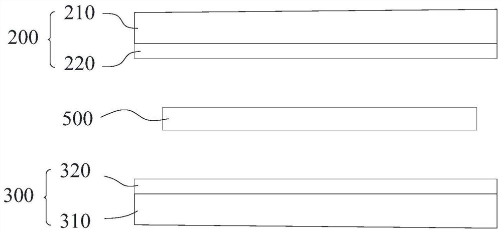
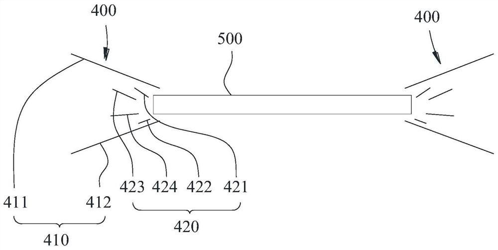
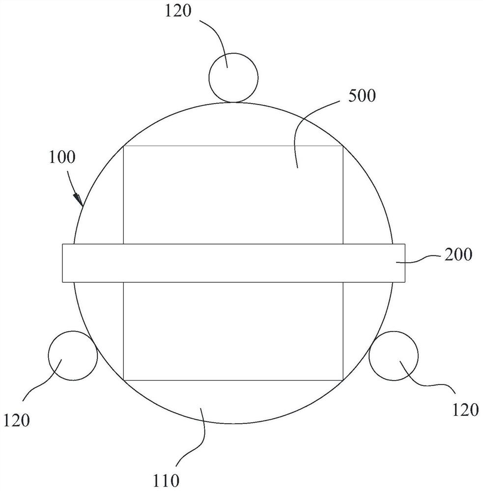
[0028] see Figure 1 to Figure 3 , the reticle manufacturing apparatus includes a supporting structure 100 , a first liquid atomization assembly 200 , a second liquid atomization assembly 300 and an airflow diversion assembly 400 .

[0029] The supporting structure 100 is used to support the reticle 500 and place the reticle 500 horizontally. The supporting structure 100 can also drive the reticle 500 to rotate around a rotation axis extending up and down; in this embodiment, the reticle 500 is square plat...


PUM


Abstract

The invention belongs to the field of mask plate manufacturing, and particularly relates to a mask plate manufacturing device which comprises a bearing structure, a first liquid atomization assembly and a secondliquid atomization assembly. The first liquid atomization assembly comprises a first particle uniform distribution plate and a first liquid high-frequency ultrasonic atomizer; the second liquid atomization assembly comprises a second particle uniform distribution plate and a second liquid high-frequency ultrasonic atomizer, and the two airflow drainage and diffusion assemblies are arranged on the left side and the right side respectively. The airflow drainage and diffusion assembly comprises a flow equalizing structure and an airflow generation device. The flow equalizing structure comprises an upper flow equalizing plate and a lower flow equalizing plate which are arranged up and down. The optical structure layers obtained on the upper surface and the lower surface of the mask plate at the same time are uniform in thickness and consistent in density.

Description

technical field [0001] The invention belongs to the field of mask plate manufacturing, in particular to a mask plate manufacturing device. Background technique [0002] For the optical structure layer on the upper surface and the lower surface of the mask, that is, the anti-reflection coating, it is usually formed by spraying an optical liquid on the mask, wherein, because the spray dose is difficult to control, this makes the optical structure layer There are problems of inconsistent thickness and density. Contents of the invention [0003] The purpose of the present invention is to overcome the shortcomings of the above-mentioned prior art, and to provide a mask manufacturing device, which aims to solve the problem of inconsistent thickness and density of the optical structure layer. [0004] The present invention is achieved like this: [0005] A mask manufacturing device, comprising: [0006] The supporting structure is used to support the reticle, and can drive the...

Claims


Application Information

Patent Timeline
Patent Type & Authority Applications(China)
IPC IPC(8): G03F1/68B05B17/06
CPCG03F1/68B05B17/06
Inventor 叶小龙侯广杰黄执祥谢超
Owner 深圳市龙图光罩股份有限公司
Why Eureka
Try Eureka