Supercharge Your Innovation With Domain-Expert AI Agents!

Power supply circuit of excitation coil of electromagnet

A technology of electromagnet coil and power supply circuit, which is applied in the direction of electromagnet, coil and circuit with armature, can solve the problems of slow output of electromagnet, difficult to control the length of delay time, and delayed closing.

Inactive Publication Date: 2004-01-28
SCHNEIDER ELECTRIC IND SAS
View PDF1 Cites 0 Cited by
  • Summary
  • Abstract
  • Description
  • Claims
  • Application Information

AI Technical Summary

Problems solved by technology

However, the choice of the length of this delay time is difficult to control
Switching may actually occur before the magnetic circuit closes, in which case the solenoid may close, but not maintain the engaged position, or it may close too late, causing the coil to overheat and reduce the solenoid's operating output. slow

Method used


Image

  • Power supply circuit of excitation coil of electromagnet
  • Power supply circuit of excitation coil of electromagnet
  • Power supply circuit of excitation coil of electromagnet

Examples


Embodiment Construction

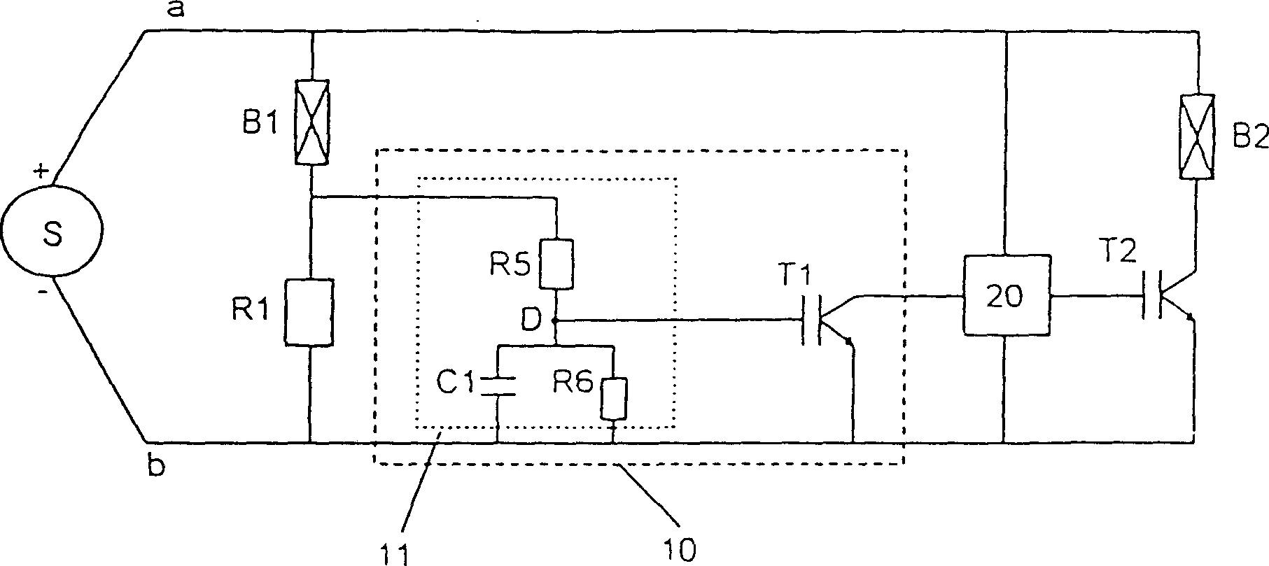
[0018] figure 1 Shown in is the power supply circuit of the electromagnet excitation coil of the present invention.

[0019] exist figure 1 The electromagnet not shown in includes an exciting coil, a fixed magnetic circuit, and a movable magnetic circuit that can be attracted by the fixed magnetic circuit when power is supplied to the coil. The coil of the electromagnet is equipped with two windings, namely a main winding B1 and a secondary winding B2.

[0020] The windings B1 and B2 are arranged in parallel between two power supply lines, and the outer lead a and the return line b are linked to the positive pole and the negative pole of the current source S, respectively. This circuit can be operated by a DC current source ( Figures 1 to 3 ) or rectified AC current ( Figure 4 ) to drive.

[0021] The main winding B1 and the secondary winding B2 can drive the moving magnetic circuit to move. The main winding B1 is continuously powered alone to maintain the active magne...


PUM


Abstract

The invention relates to a power supply circuit of the alternating current of the commutate or the direct current of the solenoid coil, which comprises a switching device (10) of a first controlled conduction semiconductor component (T2), the switching device can provide or block the power of a secondary winding (B2). The switching device (10) is arranged between a principal windings (B1) and the semiconductor component (T2), and the invention also comprises a second semiconductor component (T1) and a control terminal which is connected to the principal windings (B1) and the second semiconductor component (T1), the second semiconductor component (T1) is connected to the first semiconductor component (T2), and the semiconductor component (T2) is blocked when the voltage between the control terminal and the output of the second semiconductor component (T1) reaches a threshold voltage (Vs), and the threshold voltage is greater than the corresponding value (Vs) when the electromagnet is closed.

Description

technical field [0001] The invention relates to a power supply circuit for direct current or rectified alternating current for the field coil of an electromagnet comprising at least one principal winding and one secondary winding. Background technique [0002] Electromagnets using double wound coils are known, the effect of which is to reduce the overheating of the coil and the current draw required to power it. The coil for this purpose consists of a field winding and a holding winding. [0003] When the windings are connected in parallel, first provide a strong excitation current to the two, so that the active magnetic circuit of the electromagnet starts to move, and then only provide a weak current to the holding winding, so that the active magnetic circuit is maintained at the pull-in position, and the switch is used to stop the magnetic circuit. The action winding supplies power. [0004] From DE 2128651 it is known to electronically switch the power supply to one of ...

Claims


Application Information

Patent Timeline
IPC IPC(8): H01H47/04H01F5/04H01F7/18H01H47/08H01H47/32
CPCH01F2029/143H01F7/1833
Inventor 卡里姆·本卡罗恩曼纽尔·利马阿兰·戈塞特
Owner SCHNEIDER ELECTRIC IND SAS
Features
  • R&D
  • Intellectual Property
  • Life Sciences
  • Materials
  • Tech Scout
  • Unparalleled Data Quality
  • Higher Quality Content
  • 60% Fewer Hallucinations
Learn More