Forced ventilation and heat dissipation device for house

A technology of forced ventilation and heat dissipation device, which is applied in substation/distribution device shell, substation/switchgear cooling/ventilation, substation/switch layout details, etc., which can solve the problems of unable to realize house sealing and unsatisfactory heat dissipation effect, etc. Achieve the effect of good use effect, good heat dissipation effect and easy to extinguish

Pending Publication Date: 2021-11-16
SICHUAN POWER EHV OVERHAUL
View PDF0 Cites 0 Cited by
  • Summary
  • Abstract
  • Description
  • Claims
  • Application Information

AI Technical Summary

Problems solved by technology

[0003] The technical problem to be solved by the present invention is that the ventilation and heat dissipation device of the existing building in the substation is natural ventilation and heat dissipation, and the heat dissipation effect is not ideal. At the same time, when the house in the substation is on fire, the sealing of the house cannot be realized. The purpose is to provide a A kind of house forced ventilation heat dissipation device solves the problems encountered in the above-mentioned background technology

Method used


Image

  • Forced ventilation and heat dissipation device for house
  • Forced ventilation and heat dissipation device for house
  • Forced ventilation and heat dissipation device for house

Examples


Embodiment 1

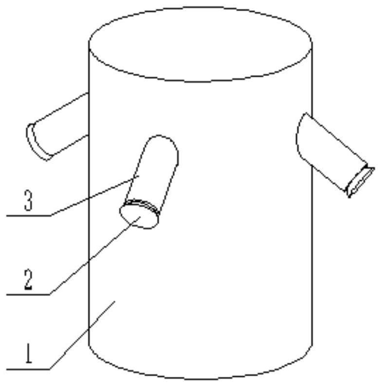
[0031] In the house forced ventilation cooling device in this embodiment, in order to achieve a better ventilation and heat dissipation effect, four air outlet tubes 1 and four air inlet pipes 6 are installed; the four air outlet tubes 1 are all installed on the top wall of the house. , and at a certain distance; four air inlet pipes 6 are installed through the side walls of the house near the ground; for example, if the house has four walls, each wall is installed with an air inlet pipe 6 near the ground;

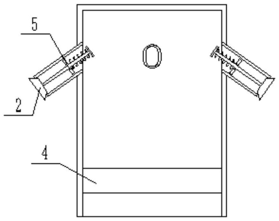
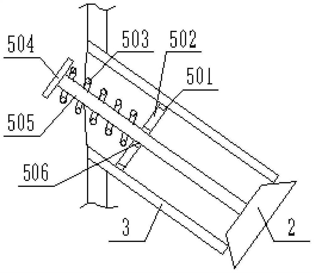
[0032] One end of the air outlet tube 1 is open and the other end is sealed, the end of the air outlet tube 1 opening is located inside the house, and the sealed end of the air outlet tube 1 is located outside the house; the inside of the air outlet tube 1 is equipped with an exhaust fan 4 near the opening end; A plurality of exhaust pipes 3 are installed on the outside of the air outlet tube 1 near the sealed end, and the plurality of exhaust pipes 3 are all located on the...

Embodiment 2

[0041] The house forced ventilation heat dissipation device in this embodiment is equipped with two air outlet tubes 1 and two air inlet pipes 6; the two air outlet tubes 1 are all installed in the side wall of the house at a higher position from the ground, and At a certain distance; two air inlet pipes 6 are installed through the side wall of the house close to the ground, and at a certain distance; for example, if the house has four walls, the two air outlets 1 can be arranged on the opposite two walls At a higher position from the ground, the two air inlet pipes 6 can be arranged on the two opposite walls close to the ground.

[0042] One end of the air outlet tube 1 is open and the other end is sealed, the end of the air outlet tube 1 opening is located inside the house, and the sealed end of the air outlet tube 1 is located outside the house; the inside of the air outlet tube 1 is equipped with an exhaust fan 4 near the opening end; A plurality of exhaust pipes 3 are ins...


PUM


Abstract

The invention discloses a forced ventilation and heat dissipation device for a house. The forced ventilation and heat dissipation device comprises at least one air outlet cylinder and at least one air inlet pipe. The air outlet cylinder is installed on the top wall of the house in the transformer substation in a penetrating mode. One end of the air outlet cylinder is opened and the other end is sealed, the open end of the air outlet cylinder is located on the inner side of the top wall of the transformer substation in-station house, and the sealed end of the air outlet cylinder is located on the outer side of the top wall of the transformer substation in-station house. An exhaust fan is mounted at one end close to the opening in the air outlet cylinder; a plurality of exhaust pipes are mounted outside the air outlet cylinder close to the sealed end, and are positioned on the outer side of the top wall of the transformer substation in-station house; the air inlet pipe is installed on the side wall of the transformer substation in-station house in a penetrating mode. A sealing plate is hinged to the end, located in the substation house, of the air inlet pipe, and an elastic telescopic rod used for driving the sealing plate to seal the air inlet pipe is hinged to the interior of the air inlet pipe. Forced ventilation and heat dissipation of the transformer substation in-station house are achieved, and the transformer substation in-station house is separated from the outside air when a fault occurs.

Description

technical field [0001] The invention relates to a ventilation and heat dissipation device, in particular to a forced ventilation and heat dissipation device for a house. Background technique [0002] Substation refers to the place where the voltage and current are transformed, received and distributed in the power system. Since there are a large number of protective screen cabinets, communication equipment and other devices in the substation, it plays a key role in the safe and stable operation of the substation. However, these The device will generate a lot of heat during the working process. In order to ensure the safety of the houses in the substation and ensure the safe and stable operation of the substation, it is necessary to use ventilation and cooling devices to ventilate and dissipate the houses in the substation. However, the current ventilation and heat dissipation device of the house in the substation is natural ventilation and heat dissipation, and the heat diss...

Claims


Application Information

Patent Timeline
Patent Type & Authority Applications(China)
IPC IPC(8): H02B1/56H02B1/28H02B7/06A62C3/16
CPCH02B1/565H02B1/28H02B7/06A62C3/16
Inventor 唐乐谕廖立茜熊晓宇唐晨晖丁嘉亿冷代军周学亿周元伟王胜尧文宗林刘凯詹育峰何霄
Owner SICHUAN POWER EHV OVERHAUL
Why Eureka
Try Eureka