Reference debugging device for bearing ring channel grinding

A bearing ring and grinding technology, which is applied to the parts of the grinding machine tool, the grinding frame, the grinding bed, etc., can solve the problems of low debugging efficiency, improve the debugging efficiency, increase the operating space, and facilitate The effect of debugging operations

Pending Publication Date: 2021-11-19
LUOYANG BEARING RES INST CO LTD
View PDF10 Cites 1 Cited by
  • Summary
  • Abstract
  • Description
  • Claims
  • Application Information

AI Technical Summary

Problems solved by technology

[0004] The purpose of the present invention is to provide a benchmark debugging device for bearing ring groove grinding, which is used to solve the technical problem of low debugging efficiency in the current benchmark debugging process of bearing rings and electromagnetic centerless fixtures

Method used


Image

  • Reference debugging device for bearing ring channel grinding
  • Reference debugging device for bearing ring channel grinding
  • Reference debugging device for bearing ring channel grinding

Examples


specific Embodiment 1

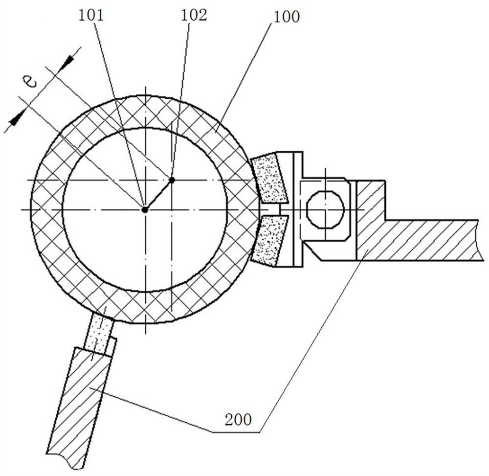
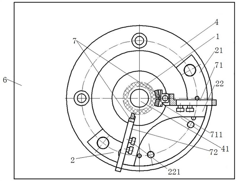
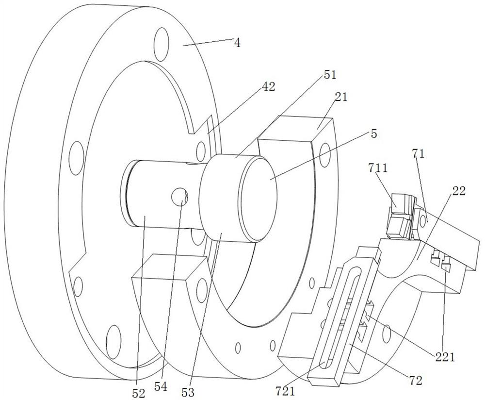
[0034] like Figure 2 to Figure 4 As shown, the reference debugging device of the present invention is based on using the electromagnetic centerless fixture 3 to act on the bearing ring 1 and drive the bearing ring 1 to rotate. In the design principle of the electromagnetic centerless fixture 3, there is a set eccentricity between the rotation axis of the bearing ring 1 and the rotation axis of the workpiece shaft of the machine tool (that is, the magnetic pole rotation axis of the electromagnetic centerless fixture 3). Under the action of the friction force between 31 and the bearing ring 1, the bearing ring 1 is driven to rotate without jumping with the magnetic pole 31 and the spindle of the machine tool, which improves the grinding accuracy of the bearing ring 1. In the present invention, in order to reduce the difficulty of debugging the rotation axis of the bearing ring and the rotation axis of the magnetic pole, the support positioning structure and the debugging seat 2...

specific Embodiment 2

[0054] In the specific embodiment 2 of a reference debugging device for bearing ring groove grinding of the present invention, the difference between this embodiment and the above embodiments is only that the supporting and positioning structure adopts the structure disclosed in the authorized publication number CN211540846U. Of course, since the electromagnetic centerless clamp is a relatively mature technology, the supporting and positioning structure is also relatively mature as a supporting technology. In other embodiments, the structure disclosed in the authorization bulletin number CN212371928U can also be used.

specific Embodiment 3

[0055] In the specific embodiment 3 of a reference debugging device for grinding a bearing ring raceway of the present invention, the difference between this embodiment and the above embodiments is only that the debugging seat is a circular ring. In other embodiments, according to actual needs, the debugging seat can also be adapted to other electromagnetic centerless clamps, such as U-shaped and the like.


PUM


Abstract

The invention relates to a reference debugging device for bearing ring channel grinding. According to the reference debugging device for bearing ring channel grinding, a debugging seat and a supporting and positioning structure are fixed to a clamp cushion plate, debugging is conducted on a workbench through a support and a debugging reference piece, and the position of the debugging reference surface relative to the debugging seat and the supporting and positioning structure is used for simulating the position of the outer circumferential surface of a bearing ring relative to the debugging seat and the supporting and positioning structure during grinding of the bearing ring. After the supporting and positioning structure and the debugging seat are debugged and fixed to the clamp cushion plate, the eccentricity of the rotation axis of the bearing ring meets the requirement. The debugging operation of the supporting and positioning structure and the debugging seat is separated from a machine tool, so that the operation space is enlarged, the debugging operation is convenient, the debugging efficiency is improved, and the technical problem of low debugging efficiency in the current position reference debugging process of the bearing ring and an electromagnetic centerless clamp is solved.

Description

technical field [0001] The invention relates to a reference debugging device used for the grinding of bearing ring grooves. Background technique [0002] When grinding the groove of the bearing ring, the electromagnetic centerless fixture is usually used for positioning. For example, the Chinese patent with the authorization announcement number CN211540846U discloses an electromagnetic centerless clamp support and positioning structure, which includes a frame and a rotating suction cup. A fixed plate is arranged outside the rotating suction cup, the fixed plate is fixed on the frame, and the fixed plate is provided with a chute. , A floating support component is arranged on the chute, and the floating support component is used to support the workpiece. When the workpiece spindle of the machine tool rotates, it can drive the electromagnetic rotating sucker to rotate, and the electromagnetic rotating sucker can adsorb the workpiece and drive the workpiece to rotate. Among th...

Claims


Application Information

Patent Timeline
Patent Type & Authority Applications(China)
IPC IPC(8): B24B19/06B24B41/06B24B41/02B24B41/00
CPCB24B19/06B24B41/06B24B41/02B24B41/00
Inventor 铁晓艳李文超张振潮侯喜林朱宇腾李东亚黄昆马新忠
Owner LUOYANG BEARING RES INST CO LTD
Why Eureka
Try Eureka