
Brake system abs road sense compensation and stroke simulation coupling control device and method

A travel simulation and coupling control technology, applied in the direction of brake transmission, brake, transportation and packaging, etc., can solve the problem of not setting and integrating ABS brake pedal feel feedback, etc., to improve braking safety and driving safety. , the effect of simple structure

Active Publication Date: 2022-04-08
HUNAN INSTITUTE OF ENGINEERING
View PDF8 Cites 0 Cited by
  • Summary
  • Abstract
  • Description
  • Claims
  • Application Information

AI Technical Summary

Problems solved by technology

And most of the existing new brake-by-wire systems are not set and integrated with corresponding ABS brake pedal sensory feedback

Method used


Image

  • Brake system abs road sense compensation and stroke simulation coupling control device and method
  • Brake system abs road sense compensation and stroke simulation coupling control device and method
  • Brake system abs road sense compensation and stroke simulation coupling control device and method

Examples


Embodiment Construction

[0023] The present invention will be further described below in conjunction with the accompanying drawings.

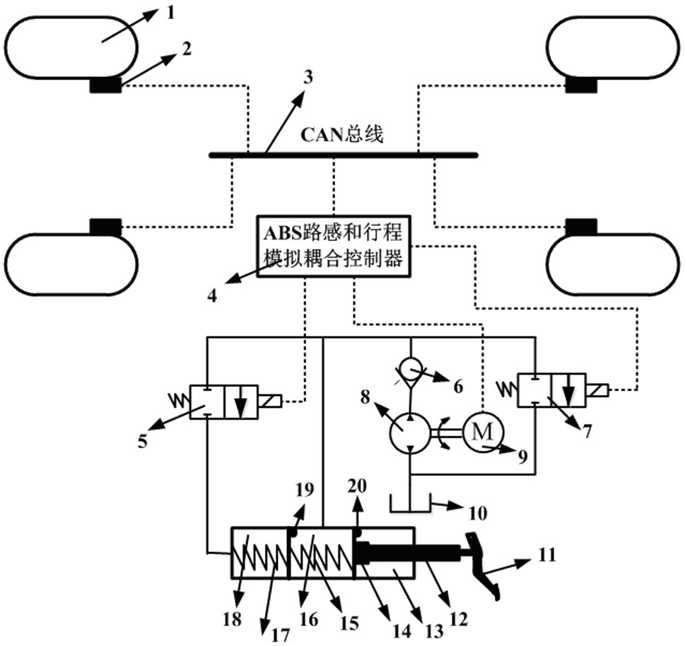
[0024] Such as figure 1 As shown, the brake system ABS road sense compensation and stroke simulation coupling control device of the present invention includes a wheel 1, an EMB system 2, a CAN bus 3, an ABS road sense and stroke simulation coupling controller 4, a first high-speed switching valve 5, Check valve 6, second high-speed switching valve 7, oil pump 8, motor 9, oil tank 10, brake pedal 11, input push rod 12, force sensor 14, brake master cylinder, rod chamber 13, first oil chamber 16. The first spring 15 , the second oil chamber 18 , the first limit rod 20 , the second limit rod 19 and the second spring 17 . The wheel 1 is connected to the EMB system 2, the EMB system 2 is connected to the CAN bus 3 through a signal line, and the CAN bus 3 is connected to the ABS road sense and stroke simulation coupling controller 4 through a signal line to realize the EMB ...

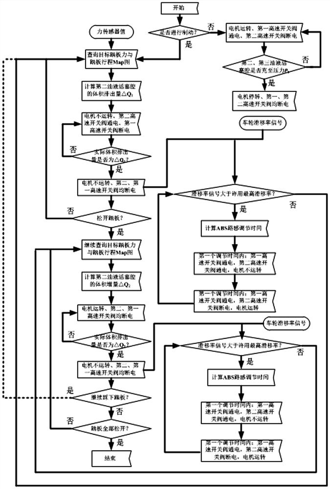

PUM


Abstract

The invention discloses a brake system ABS road sense compensation and stroke simulation coupling control device and method, the device includes a wheel, an EMB system, a CAN bus, an ABS road sense and stroke simulation coupling controller, a first high-speed switch valve, a second High-speed switching valve, oil pump, oil tank, brake pedal, input push rod, force sensor and brake master cylinder; the wheels are connected to the EMB system, the EMB system is electrically connected to the CAN bus, and the CAN bus is coupled with ABS road sense and stroke simulation The controller is electrically connected; the ABS road sense and stroke analog coupling controller are respectively electrically connected to the first high-speed on-off valve, the second high-speed on-off valve and the motor. The present invention has simple structure and low cost, and uses the ABS road sense and stroke simulation coupling controller to intervene on the first high-speed on-off valve, the second high-speed on-off valve and the motor, and can take into account the ABS road sense under the premise of realizing the pedal stroke simulation , significantly improve the braking quality of the brake-by-wire system.

Description

technical field [0001] The invention relates to a braking system ABS road sense compensation and stroke simulation coupling control device and method. Background technique [0002] The development of the new four modernizations of today's automobiles—electrification, intelligence, networking, and sharing—puts forward many new demands on automobile braking systems. Traditional braking systems have been difficult to meet, and a new type of brake-by-wire system has emerged as the times require. . The brake-by-wire system is an advanced electronically controlled new automobile braking system. It is composed of a built-in pedal displacement sensor, a pedal feeling simulator, a motor, a reduction transmission mechanism, a brake master cylinder, a housing, and a controller. The traditional vacuum booster brake system is a purely mechanical brake system that relies on vacuum to achieve boost, while the wire-controlled electronic hydraulic brake system uses the motor as the power s...

Claims


Application Information

Patent Timeline
Patent Type & Authority Patents(China)
IPC IPC(8): B60T8/40B60T8/1755B60T13/14B60T13/68
CPCB60T8/409B60T8/1755B60T8/17551B60T13/142B60T13/141B60T13/686
Inventor 王高升肖培杰张鸣
Owner HUNAN INSTITUTE OF ENGINEERING
Learn More