

Gear rack lifting appliance electromagnetic pulling flat layer control safety braking device
A technology of lifting equipment and safety braking, which is applied in the direction of elevators, hoisting devices, transportation and packaging, etc., and can solve problems such as potential safety hazards
- Summary
- Abstract
- Description
- Claims
- Application Information
AI Technical Summary
Problems solved by technology
Method used
Image

Examples
Embodiment 1
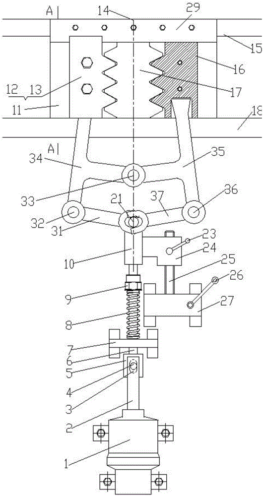
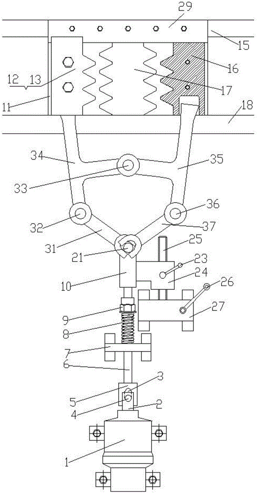
[0023] Example 1, Figure 8 It is a schematic diagram of Embodiment 1, and the drawing shows the appearance of the side of the lifting equipment. The electromagnetic pulling leveling control safety brake device of the rack and pinion lifting equipment is installed on the rack and pinion lifting equipment and is temporarily in the braking state. , Figure 9 It is a schematic diagram of the situation in which the rack and pinion lifting equipment equipped with the electromagnetic pull leveling control safety brake device of the embodiment 1 is in the brake release state, and the lifting equipment is ready to run or is running. The left and right mentioned above are viewed from the inside of the lifting device to the side of the lifting device. Figure 8 , Figure 9 It is viewed from the outside to the side of the lifting equipment, so the left and right directions are just opposite), the electromagnetic pull leveling control safety brake device of the rack and pinion lifting e...
Embodiment 2
[0024] Embodiment 2 is a lifting device equipped with the rack and pinion lifting device according to the present invention, which is equipped with an electromagnetic pulling leveling control safety brake device, Figure 10 It is a schematic diagram of embodiment 2, showing that the main body of the electromagnetic puller 1 is in a power-off state, and the situation when the electromagnetic pull leveling control safety braking device implements braking, Figure 11 In Example 2, when the main body 1 of the electromagnetic puller is in the energized state and the electromagnetic pull leveling control safety brake device is in a free position state, the rack and pinion lifting equipment used in the electromagnetic pull leveling control safety brake device is specific The structure is an independent electromagnetic pull leveling control safety brake device component that is separately set up as an independent component and then installed on the lifting equipment. Its structure and ...
Embodiment 3
[0025] Embodiment 3, an elevator equipped with a lifting equipment electromagnetic pull leveling control safety brake assembly directly installed on the lifting equipment, its appearance is the same as Figure 8 , Figure 9 , the working principle is the same as described in paragraph [0023].
PUM
 Abstract
Description
Claims
Application Information